Installation & Application Guide
Delta Field Module (4 Pulse Inputs)
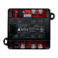
DFM-400P (Rev 1.2)
Product Description
The Delta Field Modules are small expansion I/O boards
that provide remotely expandable I/O to Delta’s BACnet
Controllers. The DFM-400P Pulse Input Field Module
provides four pulsed inputs and communicates directly on
a BACnet RS-485 MS/TP network where it functions as an
independent BACnet device and the pulse counter values
and PI objects are accessible over the MS/TP network.
Ideal for electrical, water, gas, and various flow meters,
the DFM-400P has four pulse inputs. Two inputs support
pulses from 0 to 200 Hz and the other two inputs support
pulses from 0 to 2000 Hz.
Any additional strategies associated with the pulse
counter values are typically programmed in GCL in other
controllers on the network.
Contents
Model Numbers.......................................................................................................................... 2
Package Contents ...................................................................................................................... 2
Other Relevant Documents ........................................................................................................ 2
Important Information ............................................................................................................... 2
Product Specifications ............................................................................................................... 3
Board Layout (DFM-400P) .......................................................................................................... 4
Device Address DIP Switches .................................................................................................... 5
Indicators ................................................................................................................................... 5
Jumpers ..................................................................................................................................... 5
Mounting .................................................................................................................................... 7
Input Wiring ................................................................................................................................ 7
Power ......................................................................................................................................... 7
Network & Cabling Requirements ............................................................................................. 7
Network Topology ...................................................................................................................... 8
Network Communications Setup ............................................................................................... 8
Application Notes ....................................................................................................................... 9
Cautions and Warnings ............................................................................................................ 13
Compliance Declarations ......................................................................................................... 13