DFM-400P Rev 2.1 Installation and Appplication Guide Edition 1.6
Page 5 of 14
Device Address DIP Switches
Each individual DIP switch represents a unique value, which forms the device address when added
together.
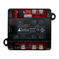
Indicators
Power Power Indicator
This amber (or red on early boards) LED turns
on to indicate that the controller has power
applied.
Scan CPU Scan Indicator
This red LED indicates CPU integrity by blinking
every second.
(NET1)
RS-485 Communication Status
Indicators for NET1
A green LED flashes to indicate when the device
is transmitting out the associated port, and a red
LED flashes to indicate when the device is
receiving data through the port.
Jumpers
Debounce circuitry, which may be necessary for dry/mechanical
contacts, may be enabled or disabled per pulsed input with this jumper
setting – but is limited to pulses less than 200 Hz.
Enabled With the jumper in place, debounce circuitry is connected
in circuit. Do not use this setting with open collector pulse
inputs.
Disabled Without the jumper, debounce circuitry is
not
connected in
circuit.
NETWORK CONNECTION (No Jumper)
Not applicable – there is no jumper. This module is fixed so that it may
only be connected directly on a BACnet RS-485 MS/TP network. Do
not connect this module to a LINKnet network.
 Loading...