8
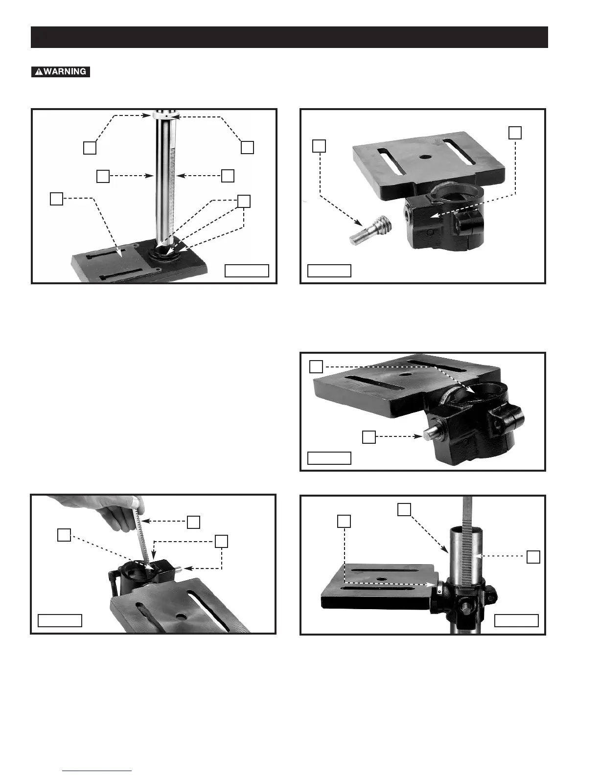
1. Attach the column (A) Fig. 3 to the base (B) using the four M8x1.25x25mm hex head screws (C), three of which
are shown. Loosen the set screw (D) and remove the ring (E) and raising rack (F).
2. Place the worm gear (G) Fig. 4 in the table bracket (H).
3. Insert the raising rack (F) Fig. 6 (removed in STEP 1) in the table bracket groove (
I).
NOTE: Place the teeth of the raising rack (F) in the teeth of the worm gear (G) located inside table bracket.
4. Slide the raising rack (F) Fig. 7and the table with the table bracket (J) on the drill press column (K) Fig. 7.
ASSEMBLY
For your own safety, do not connect the machine to the power source until the machine is
completely assembled and you read and understand the entire instruction manual.
A
E
F
D
C
B
Fig. 3
Fig. 4
Fig. 5
NOTE: Place the small end of the worm gear (G) Fig. 5
in the hole (J), then into the hole for the worm gear. The
correct placement is shown in Fig. 5.
G
H
G
J
Fig. 6
Fig. 7
F
G
J
K
F
I
 Loading...