9
Fig. 8
Fig. 11
Fig. 12
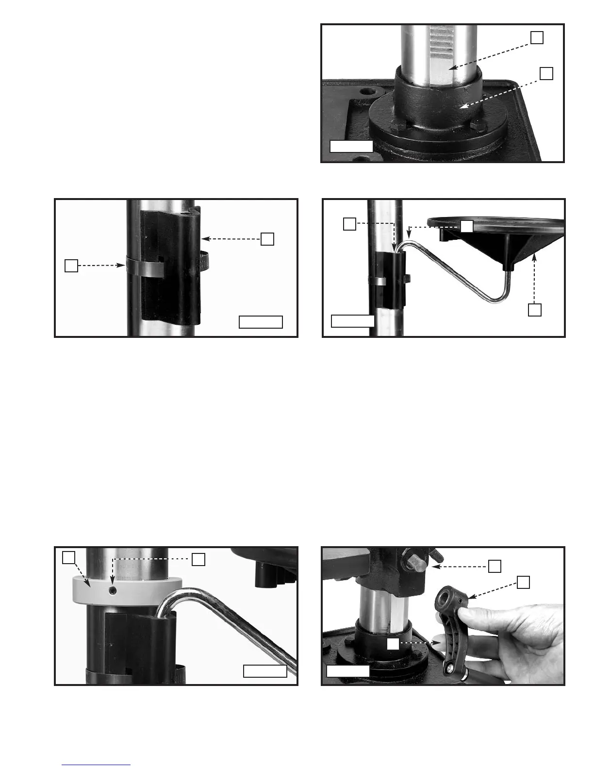
5. Place the mounting bracket (A) Fig. 9 on the column.
NOTE: To avoid interference with the spindle height adjusting handles (P) Fig. 16, place the mounting bracket on the
opposite side of the column from the raising rack.
6. Insert the hose clamp (B) Fig. 9 through the mounting bracket, under the raising rack, and around the column.
Tighten the hose clamp securely.
7. Slide the mounting arm (C) with the tray (A) into the bracket (D) (Fig. 10).
8. Install the ring (E) Fig. 11 (removed in STEP 1) on the column.
IMPORTANT: Place the raising rack under the bottom of the ring, but allow enough clearance so that the rack (F) can rotate
around the column. Tighten the set screw (D) Fig. 11.
9. Attach the table raising and lowering handle (K) Fig. 12 on the worm gear shaft (G) and tighten the set screw (L)
against the flat on the shaft.
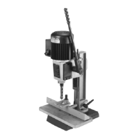
NOTE: Place the bottom of the raising rack (F) Fig. 8
inside the flange (L) on the drill press base.
F
L
Fig. 9
A
B
Fig. 10
Fig. 8
D
C
A
D
E
G
L
K
Fig. 11 Fig. 12
 Loading...