17
3 Installation
Read all of these instructions, cautions, and warnings for the Delta
M series inverter and associated PV array documentation.
Lisez toutes les instructions, rubriques Prudence et Avertissement
de l’onduleur Delta M series , ainsi que la documentation sur le
panneau photovoltaïque associé.
Installation and commissioning must be performed by a licensed
electrician in accordance with local, state, and National Electrical
Code ANSI/NFPA 70 requirements.
L’installation et la mise en service doivent être eectuées par un
électricien autorisé conformément aux exigences locales et natio-
nales ainsi qu’au National Electrical Code ANSI/NFPA 70.
The installation and wiring methods used in the installation of this
inverter in the U.S. must comply with all US National Electric Code
requirements (NEC) and local AHJ inspector requirements. In
Canada, the installation and wiring methods used must comply
with the Canadian Electric Code, parts I and II, and the local AHJ
inspector requirements. System grounding when required by the
Canadian Electrical Code, Part 1, is the responsibility of the
installer.
Les méthodes d’installation et de câblage utilisées lors de
l’installation de cet onduleur aux États-Unis doivent être conformes
à toutes les exigences du National Electric Code (NEC) nord-
américain et à celles des services d’inspection locaux de l’AHJ. Au
Canada, les méthodes d’installation et de câblage utilisées doivent
être conformes au Canadian Electric Code, parties I et II et aux
exigences des services d’inspection locaux l’AHJ. L’installateur est
responsable de la mise à terre du système lorsque requise par le
Canadian Electrical Code, Partie 1.
WARNING!
AVERTISSEMENT!
WARNING!
AVERTISSEMENT!
WARNING!
AVERTISSEMENT!
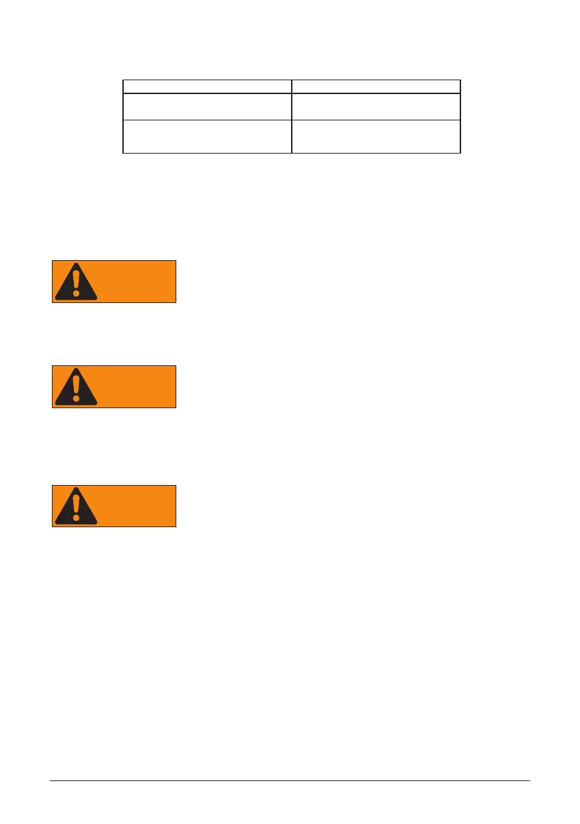
Required torques for wiring box terminals
Table 1: Required torques for wiring box terminals
* Exception: Specied torque marked on the terminal block.
Terminals in Figure 12 Wire size permitted
3,(see location and description
above)
14 - 8 AWG (2.5 - 9 mm
2
)
1, 4, 5, 6, 7(see location and
description above)
14 - 6 AWG (2.5 - 16 mm
2
)
 Loading...


