43
The inverter feeds in grid.
Four LEDs form
a progress bar.
The inverter is synchronizing with
grid.
LED signals:
OPER LED is ON,
BAT LED is ON.
COMM LED Blinks
Message:
Synchronization progress
is 50%-75%.
Grid is connected, but the inverter
is unable to feed in grid because
PV voltage is too low.
Battery is in fault mode.
Battery communication timeout
Battery is in standby mode
Absolute battery power is lower
than 50W
Battery is in normal operation.
Only BLINK for 2 cycles in
one minute
INFO Led
Firmware
upgrading
INFO Yellow <BLINK> 1s on, 1s off Firmware upgrading is ongoing
Receiving
image
INFO Green <BLINK> 1s on, 1s off Inverter is receiving image file
Equipment
alarm
INFO Yellow <ON> Constant on External event occurs and inverter
is unable to run
FAULT Led
Arc fault FAULT Red <ON> Constant on Arc fault occurs
Ground fault FAULT Red <BLINK> 1s on, 1s off Ground fault occurs
Other
Initialization OPER Green <ON> On until done I
nverter initialization when grid is
changing from disconnected into
connected.
BAT Green <ON> On until done
COMM Green <ON> On until done
INFO Green <ON> On until done
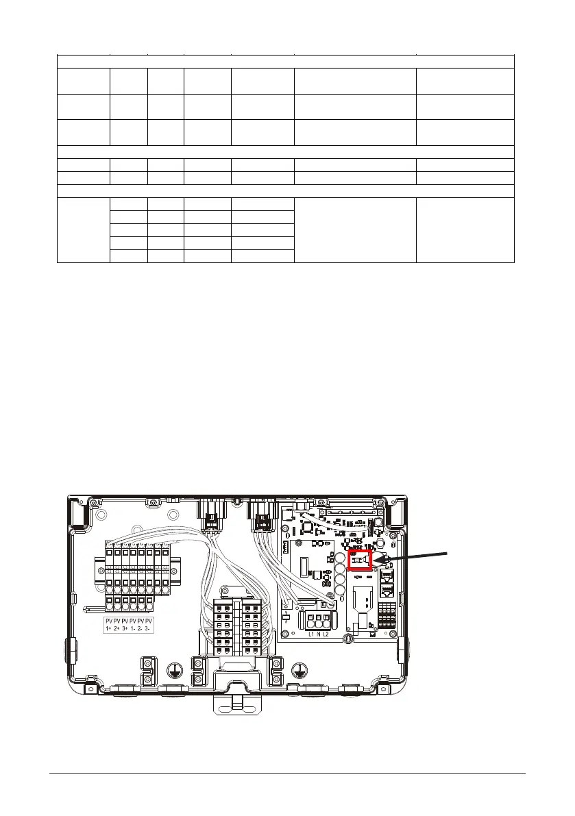
5.2 Button
There is button located inside the junction box, for this button, there are following functions.
1. Arc reset
Application: Clear arc fault.
Trigger condition: Press the button for 3-5 seconds.
2. Arc self-test
Application: If there is no arc fault, run arc self-test
Trigger condition: Press the button for 3-5 seconds.
2. Gateway reset
Application: gateway reset to factory status
Trigger condition: Press the button for more than 10 seconds.
5.2.1 Reset button
Reset button