35
INFORMATION!
INFORMATIONS!
All screw terminals accept solid or stranded copper DC:14 – 8
AWG wire,AC: 14 – 6 AWG wire.
Toutes les bornes à vis n‘acceptent que les ls de cuivre rigides
ou souples de DC:14 – 8 AWG ,AC: 14 – 6 AWG. I
.
The AC output (neutral) is not bonded to ground in the inverter.
La sortie de courant alternatif (neutre) n’est pas lié à la masse de
l‘onduleur.
INFORMATION!
INFORMATIONS!
Conduit ttings need to be water tight with either NEMA 4, 4X, 6, or 6X rated, and insulated type
preferred.
Once conduit and ttings are installed, route wiring thru conduit and tting and allowing a 6 inch
strain relief loop within the wiring box compartment.
Potential AC voltage loss in AC wires is possible to determine for a given wire cross section
and wire length. Pages 59 and 60 contain diagrams for each M series solar inverter model to
help determine the best wire size for your particular installation. Delta recommends you select
a wire size and length to ensure a maximum voltage loss between 1 - 2 %. Please note that the
diagrams only oer approximate voltage loss and more precise voltage loss should be calculated
by a licensed electrician in accordance with local, state, and National Electrical Code ANSI/NFPA
70 requirements.
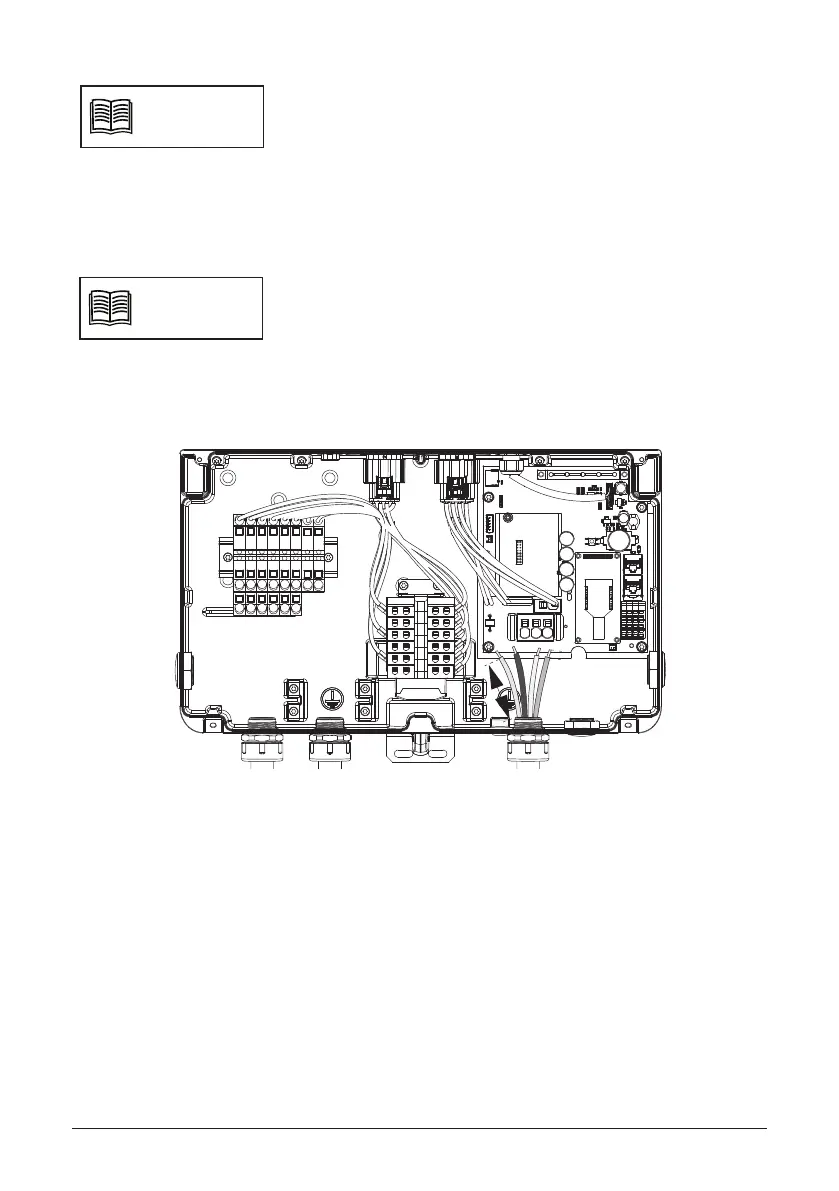
Figure 28: Conduit installation and AC wiring routing
6 inchs
0.7 inchs
 Loading...


