39
Interface connection RS485 (EIA485)
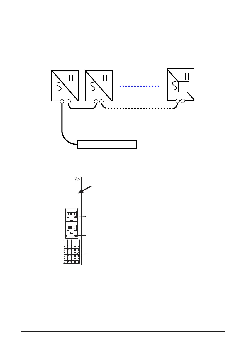
The Delta M series inverters oer an EIA RS485 communication interface which can address
up to 31 daisy chained inverters. For optimal performance, all unused interface connections must
always be terminated by placing the termination jumper in the “on” position.
Figure 32: Inverter RS485 system diagram
TERM.
ON
Gateway or Datalogger
INV 1 INV 2
INV 31
RS485
J1
J2
RS485
J1
J2
RS485
J1
J2
J1=RS485 port 1
J2=RS485 port 2
The Termination Jumper is shown in the diagram on the left.
To enable termination, place the jumper over the two left pins
next to the “on” label on the board. To disable termination,
place the jumper in the o position on the right two pins.
CAN and 485 communication ports
Ethernet and 485 communication ports
RGM communication ports
Figure 33: RS485 Termination Jumper
 Loading...


