Chapter 4 Parameters
VFD-EL-W
4-81
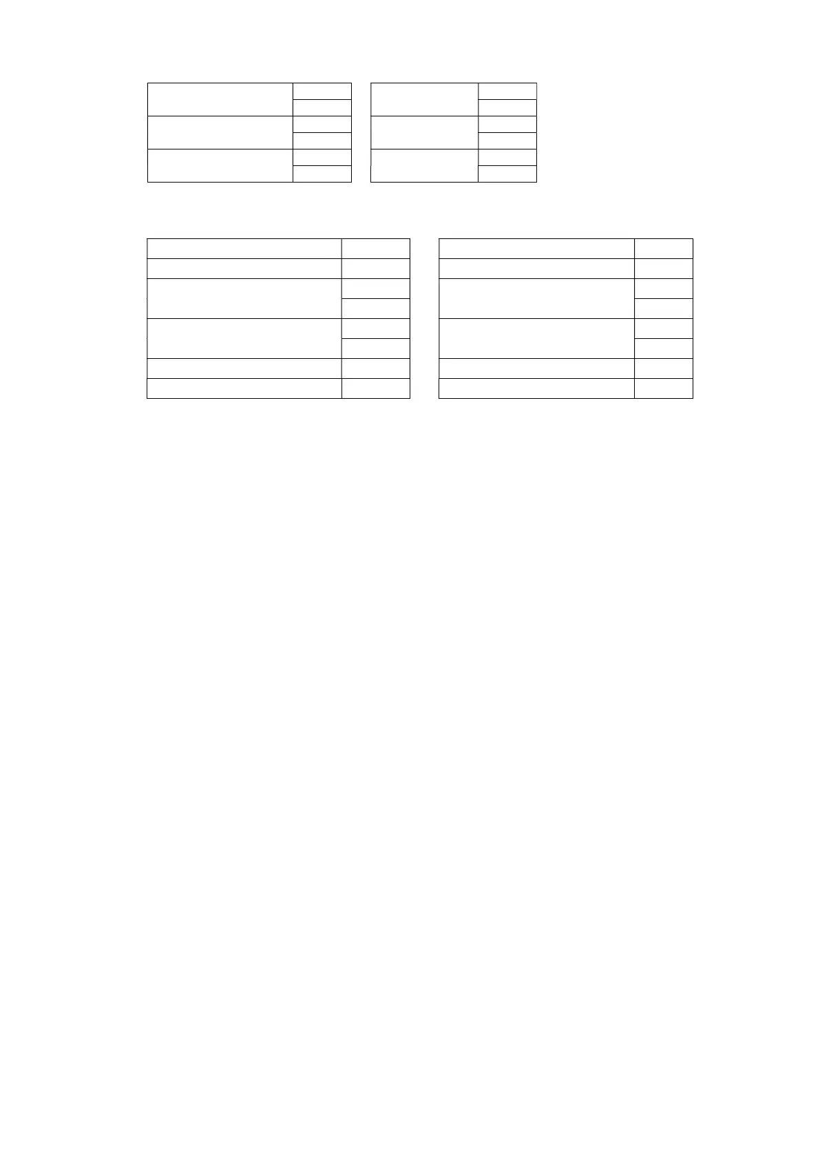
Command message:
Response message:
‘7’
‘7’
‘0’
‘0’
LRC Check
‘7’
LRC Check
‘7’
‘1’
‘1’
END
CR
END
CR
LF
LF
RTU mode:
Command message: Response message:
ADR 01H ADR 01H
CMD 08H CMD 08H
Data
00H
Data
00H
00H 00H
Data
17H
Data
17H
70H 70H
CRC CHK Low 8EH CRC CHK Low 8EH
CRC CHK High 0EH CRC CHK High 0EH
4. CRC (Cyclical Redundancy Check) is calculated by the following steps:
Step 1: Load a 16-bit register (called CRC register) with FFFFH.
Step 2: Exclusive OR the first 8-bit byte of the command message with the low order byte of the 16-bit
CRC register, storing the result in the CRC register.
Step 3: Examine the LSB of CRC register.
Step 4: If the LSB of CRC register is 0, shift the CRC register one bit to the right with MSB zero filling, then
repeat step 3. If the LSB of CRC register is 1, shift the CRC register one bit to the right with MSB zero
filling, Exclusive OR the CRC register with the polynomial value A001H, then repeat step 3.
Step 5: Repeat step 3 and 4 until eight shifts have been performed. When this is done, a complete 8-bit
byte will have been processed.
Step 6: Repeat step 2 to 5 for the next 8-bit byte of the command message. Continue doing this until all
bytes have been processed. The final content of the CRC register is the CRC value. When transmitting the
CRC value in the message, the upper and lower bytes of the CRC value must be swapped, that is the
lower order byte will be transmitted first.
The following is an example of CRC generation using C language. The function takes two arguments:
Unsigned char* data a pointer to the message buffer
Unsigned char length the quantity of bytes in the message buffer
The function returns the CRC value as a type of unsigned integer.
Unsigned int crc_chk(unsigned char* data, unsigned char length){
int j;
unsigned int reg_crc=0xFFFF;
while(length--){
reg_crc ^= *data++;
for(j=0;j<8;j++){
if(reg_crc & 0x01){ /* LSB(b0)=1 */
reg_crc=(reg_crc>>1) ^ 0xA001;
}else{
reg_crc=reg_crc >>1;
}
}
}
return reg_crc;
}