10
ENGLISH
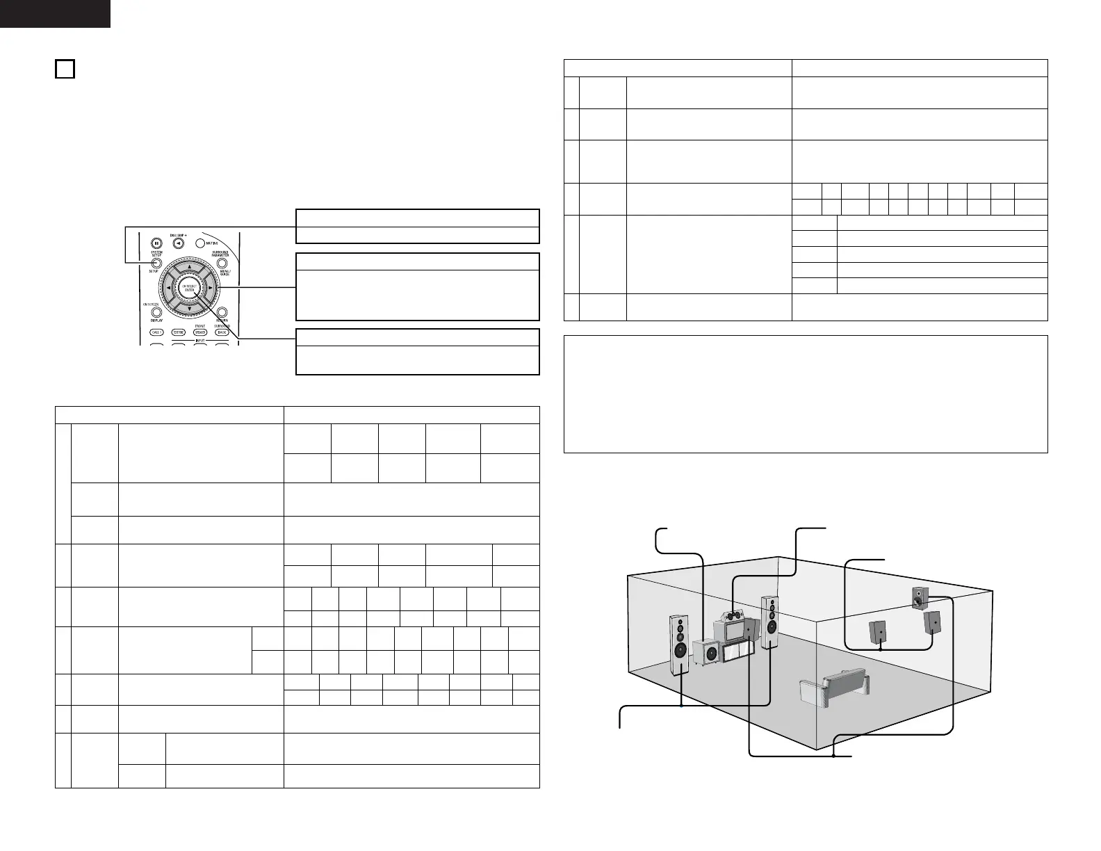
SYSTEM SETUP button
Press this to display the system setup menu.
ENTER button
Press this to switch the display.
Also use this button to complete the setting.
CURSOR buttons
0
and
1
: Use these to move the cursors (
0
and
1
) to
the left and right on the screen.
• and ª: Use these to move the cursors (• and ª) to
the up and down on the screen.
NOTES:
• The on-screen display signals are output with priority to the S-VIDEO MONITOR OUT jack during playback
of a video component. For example, if the TV monitor is connected to both the AVR-2803’s S-Video and
video monitor output jacks and signals are input to the AVR-2803 from a video source (VDP, etc.) connected
to both the S-Video and video input jacks, the on-screen display signals are output with priority to the S-
Video monitor output. If you wish to output the signals to the video monitor output jack, do not connect a
cord to the S-VIDEO MONITOR OUT jack. (For details, see page 17.)
• The AVR-2803’s on-screen display function is designed for use with high resolution monitor TVs, so it may
be difficult to read small characters on TVs with small screens or low resolutions.
• The setup menu is not displayed when headphones are being used.
• Speaker system layout
Basic system layout
• The following is an example of the basic layout for a system consisting of eight speaker systems and a
television monitor:
Subwoofer Center speaker system
Surround speaker systems
Surround back speaker systems
Front speaker systems
Set these at the sides of the TV or
screen with their front surfaces as flush
with the front of the screen as possible.
7
SETTING UP THE SYSTEM
• Once all connections with other AV components have been completed as described in “CONNECTIONS”
(see pages 4 to 8), make the various settings described below on the monitor screen using the AVR-2803’s
on-screen display function.
These settings are required to set up the listening room’s AV system centered around the AVR-2803.
• Check that the remote control unit is set to AMP mode (TAPE, CDR/MD or CD).
• The system settings can be reset to the default (factory shipment) settings by initialization of the
microprocessor (see page 37).
• Use the following buttons to set up the system:
• System setup items and default values (set upon shipment from the factory)
System setup Default settings
y
e
r
Speaker
Configuration
Subwoofer
mode
Dolby Digital
Setup
Channel
Level
Digital In
Assignment
Input the combination of speakers in your
system and their corresponding sizes (Small for
regular speakers, Large for full-size, full-range) to
automatically set the composition of the signals
output from the speakers and the frequency
response.
This selects the subwoofer speaker for playing
deep bass signals.
Turn the audio compression on or off when down-
mixing Dolby Digital signals.
This adjusts the volume of the signals output from
the speakers and subwoofer for the different
channels in order to obtain optimum effects.
This assigns the digital input jacks for the
different input sources.
Input
source
Digital
Inputs
Front Sp.
Large
Center Sp. Surround Sp.Sub Woofer
Small SmallYes
LFE
Front L & R Center Surround L & RSub Woofer
3.6 m (12 ft) 3.6 m (12 ft) 3.0 m (10 ft)3.6 m (12 ft)
Front L
Front R Center
Surround
R
Surround
Back R
Subwoofer
0 dB 0 dB 0 dB 0 dB 0 dB 0 dB
CD
DVD VDP TV DBS TAPE
COAX1 COAX2 OPT1 OPT2 OPT3 OPT4
Surround Back
Sp.
Small / 2spkrs
OFF
w
Delay Time
This parameter is for optimizing the timing with
which the audio signals are produced from the
speakers and subwoofer according to the listening
position.
SBL & SBR
3.0 m (10 ft)
Surround
Back L
0 dB
Surround
L
0 dB
VCR-1
OFF
V. AUX
OFF
q
Crossover
Frequency
Set the frequency (Hz) below which the bass sound
of the various speakers is to be output from the
subwoofer.
80 Hz
VCR-2
OFF
t
Video In
Assignment
This assigns the color difference (component)
video input jacks for the different input sources.
DVD
VDP TV VCR-1 V. AUX
—
VIDEO1 NONE NONE NONE NONE
—
VCR-2
NONE
DBS
VIDEO2
Set this to switch the surround back
channel’s power amplifier for use
for zone 2.
Surround Back
Power AMP
Assignment
This sets the output level for the
zone 2 output jacks.
Variable
Zone2 vol.
Level
u
Zone2
Control
System setup Default settings
!1
On Screen
Display
This sets whether or not to display the on-screen
display that appears on the monitor screen when
the controls on the remote control unit or main unit
are operated.
On Screen Display = ON
A1 ~ A8 87.5 / 89.1 / 98.1 / 108.0 / 90.1 / 90.1 / 90.1 / 90.1 MHz
B1 ~ B8 522 / 603 / 999 / 1404 / 1611 kHz, 90.1 / 90.1 MHz
C1 ~ C8 90.1 MHz
D1 ~ D8 90.1 MHz
E1 ~ E8 90.1 MHz
!3
Auto Tuner
Preset
FM stations are received automatically and stored
in the memory.
i
o
Ext. In
Subwoofer
Level
Set the Ext. In Subwoofer terminal playback level. Subwoofer = +15 dB
!0
Auto
Surround
Mode
Set the Auto surround mode function. Auto Surround Mode = ON
!2
Trigger Out
Setup
Set the Trigger Out output for the different input
sources.
PHONO
CD TUNER DVD TVVDP
TAPE
DBS VCR-1
OFF OFF OFF
ON ONON
OFF
ON ON
Setup Lock
Set whether or not to lock the system setup
settings so that they cannot be changed.
Setup Lock = OFF
VCR-2
ON
V. AUX
ON
 Loading...