12
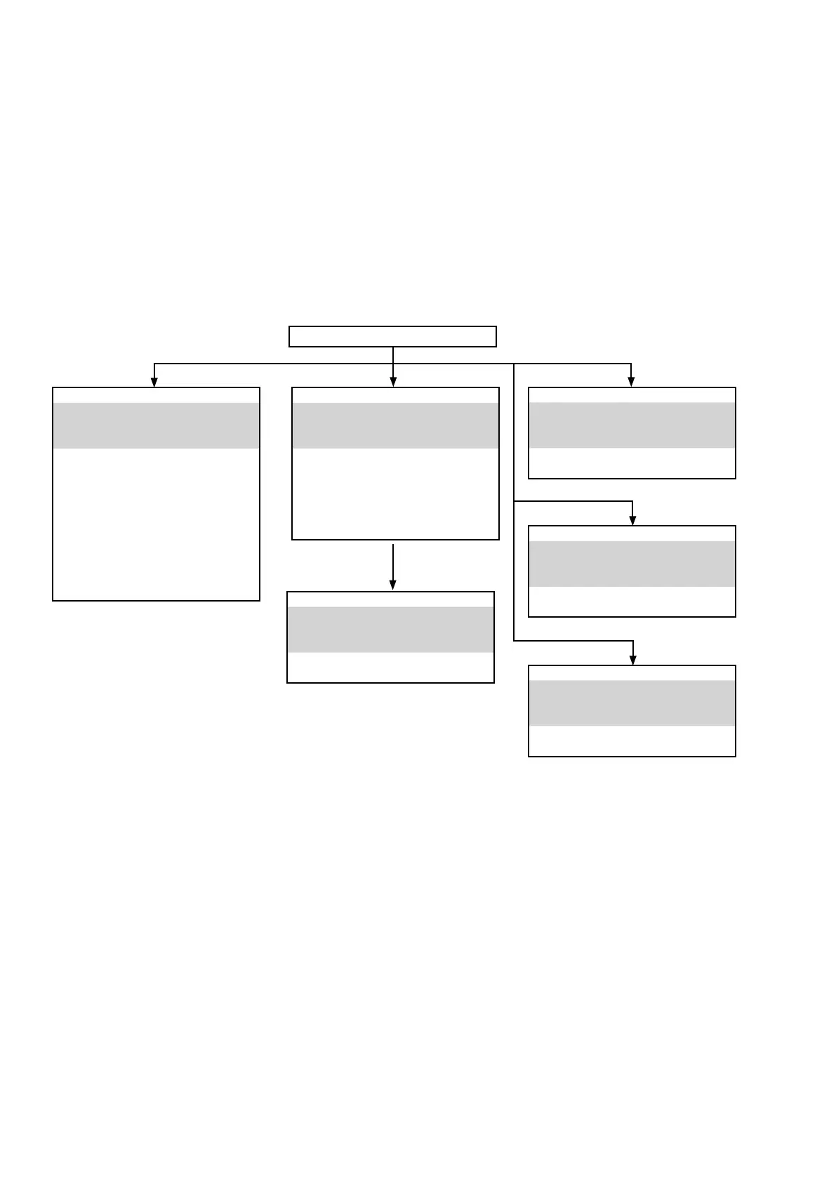
DISASSEMBLY
• Remove each part in the order of the arrows below.
• Reassemble removed parts in the reverse order.
• Read“ SAFETY PRECAUTION” before reassembling removed parts.
• If wire bundles are removed or moved during adjustment or part replacement, reshape the wires after completing the
work. Failure to shape the wires correctly may cause problems such as noise.
FRONT PANEL ASSY
See "DISASSEMBLY
1. FRONT PANEL ASSY"
and "EXPLODED VIEW"
FRONT PCB
(Ref. No. of EXPLODED VIEW : P1)
STANDBY PCB
(Ref. No. of EXPLODED VIEW : P2)
PHONE PCB
(Ref. No. of EXPLODED VIEW : P3)
USB & MIC PCB
(Ref. No. of EXPLODED VIEW : P4)
MODULE BLUETOOTH
(Ref. No. of EXPLODED VIEW : P5)
RADIATOR ASSY
See "DISASSEMBLY
3. RADIATOR ASSY"
and "EXPLODED VIEW"
MAIN PCB
(Ref. No. of EXPLODED VIEW : P6)
SMPS PCB
See "DISASSEMBLY
4. SMPS PCB
and "EXPLODED VIEW"
SMPS PCB
(Ref. No. of EXPLODED VIEW : P12)
REGULATOR PCB
See "DISASSEMBLY
5. REGULATOR PCB"
and "EXPLODED VIEW"
REGULATOR PCB
(Ref. No. of EXPLODED VIEW : P11)
TRANS POWER
See "DISASSEMBLY
6. TRANS POWER"
and "EXPLODED VIEW"
TRANS POWER
(Ref. No. of EXPLODED VIEW : P15 )
DIGITAL PCB
See "DISASSEMBLY
2. DIGITAL PCB ASSY"
and "EXPLODED VIEW"
VIDEO PCB
(Ref. No. of EXPLODED VIEW : P10)
DIGITAL PCB
(Ref. No. of EXPLODED VIEW : P8)
TUNER PCB
(Ref. No. of EXPLODED VIEW : P9)
TOP CABINET
 Loading...