19
POA-A1HDCI/POA-A1HD
SEMICONDUCTORS
Only major semiconductors are shown, general semiconductors etc. are omitted to list.
主な半導体を記載しています。汎用の半導体は記載を省略しています。
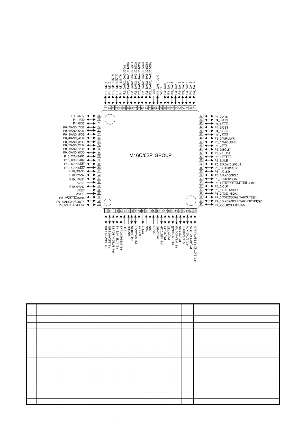
1. IC’s
M3062FLGPGP (IC307)
M3062FLGPGP
Terminal Function
※ The following table is a state when the CONTROL mode switch under the back panel is turned off.
※下記表は、バックパネル下部の CONTROL モードスイッチを OFF にした時の状態です。
Pin
No.
Pin Name Symbol I/O Type Det
Op
(Int.)
Op
(Ext.)
Res STBY stop Function
1 P94/TB4 PUP5V POWER O C - - - Z O/L O/L +B control pin for PUP 5V (Not used)
2 P93/TB3 EXP STB O C - - - Z O/L O/L STB output for expander control
3 P92/
SOUT3
EXP DATA O C - - - Z O/L O/L DATA output for expander control
4 P91/SIN3 EXP OE O C - - - Z O/L O/L OE output for expander control
5 P90/CLK3 EXP CLK O C - - - Z O/L O/L CLK output for expander control
6 BYTE BYTE - - - - - - - - GND (Ext. data bus bit width switching, 16bit : L)
7 CNVCS CNVSS I - - - Ed - - - Single-chip / Micro-processor mode switching (Nor-
mal single-chip : L,Rewrite boot program start : H
input set)"
8 XCIN/P87 R_SW5V_POWER O C - - Z O/L O/L +B control pin for INPUT SEL SW/REMOTE CON-
TROL MODE SEL SW set circuit
9 XCOUT/
P86
SW 5V POWER O C - - Z O/L O/L +B control pin for PROTECTION/EXP/PUP circuit
10 RESET RESET I - Lv - Eu L I I Reset input (reset : L)
11 XOUT XOUT O - - - - - - - Clock input
 Loading...