7
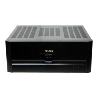
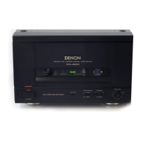
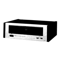
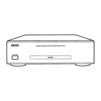
POA-A1HDCI/POA-A1HD
DISASSEMBLY
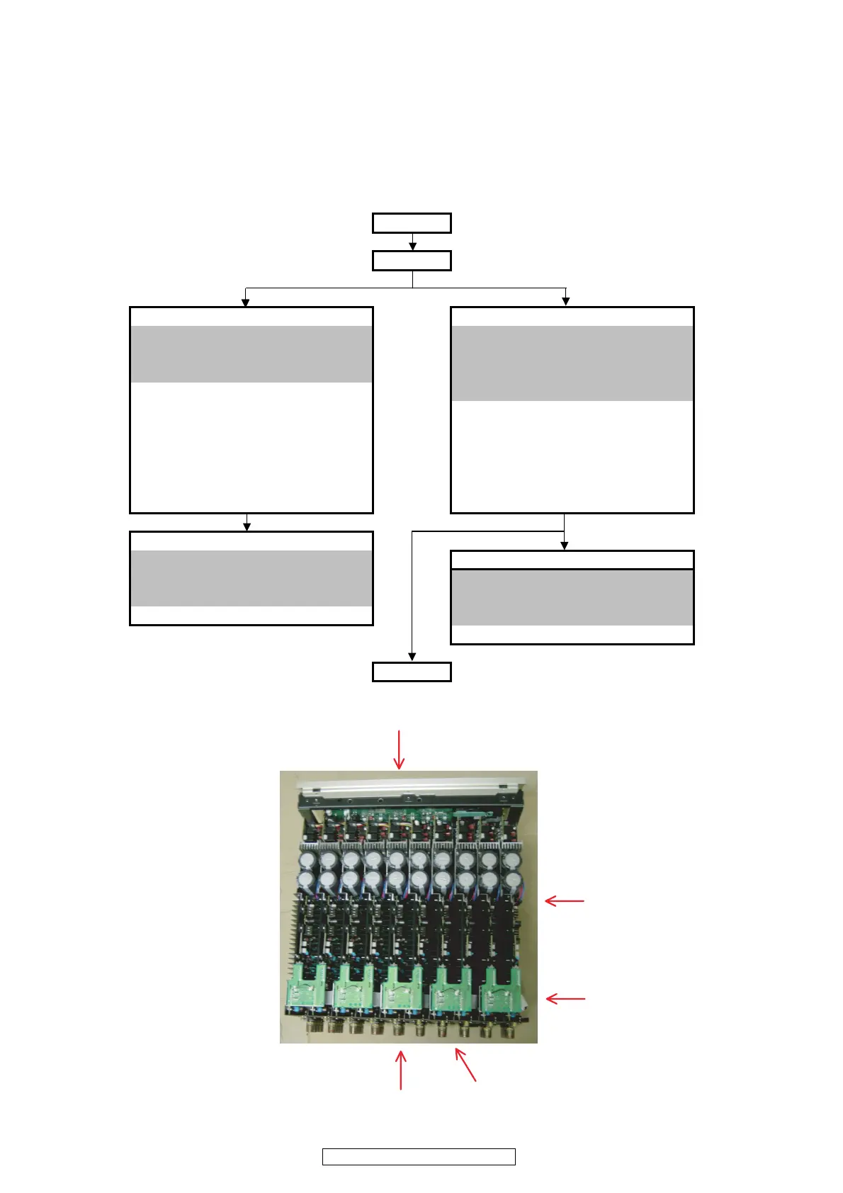
• Disassemble in order of the arrow of the figure of following flow.
下記フロー図の矢印の順番にはずしてください。
• In the case of the re-assembling, assemble it in order of the reverse of the following flow.
再組み立ての場合は、下記のフローの逆の順番に組立ててください
• In the case of the re-assembling, observe "attention of assembling" it.
再組み立ての場合は、「組立のご注意」を遵守してください。
Top cover
Side cover
Front panel sub ass'y Radiator sub ass'y
Refer to "DISASSEMBLY 1.FRONT PANEL UNIT" Refer to "DISASSEMBLY 2.RADIATOR UNIT"
and "EXPLODED VIEWS( 2/3 )" and "EXPLODED VIEWS( 3/3 )"
( FRONT PANEL UNIT ) ( RADIATORE UNIT )
1-10 : P.KEY UNIT L1
→
L2
→
L3
→
L4
→
L5
→
R5
→
R4
→
R3
→
R2
→
R1
1-11 : METER LED UNIT 3-1 : P.AMP UNIT
1-13 : P.SW UNIT 3-2 : INPUT UNIT
1-16 : TACT UNIT 3-3 : AMP SUPPLY UNIT
1-18 : METER PLATE UNIT 3-4 : HIGHBAL UNIT
2-8 : METER DRIVE UNIT 3-6 : XLR UNIT
2-9 : LED UNIT 3-7 : RCA UNIT
1-12 PRIMARY UNIT
Refer to "DISASSEMBLY 1.FRONT PANEL UNIT" Rear panel bottom ass'y
and "EXPLODED VIEWS( 1/3 )" Refer to "DISASSEMBLY 3.Raer panel bottom ass'y"
( MAIN UNIT ) and "EXPLODED VIEWS( 1/3 )"
1-12 : PRIMARY UNIT ( MAIN UNIT )
2-1 : CPU UNIT
Trans
㨇Picture A㨉
㨇Picture B㨉
㨇Picture E㨉
㨇Picture C㨉
㨇Picture D㨉
The viewpoint of each photograph
(photography direction)
ฦ࿑ߩⷞὐ㧔ᓇᣇะ㧕
㨇Top view㨉