ENGLISH
21
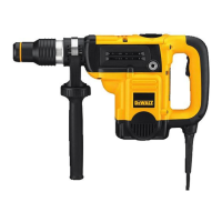
will cause a drop in line voltage resulting in loss of power
and overheating. When using more than one extension
to make up the total length, be sure each individual
extension contains at least the minimum wire size. The
following table shows the correct size to use depending on
cord length and nameplate ampere rating. If in doubt, use
the next heavier gauge. The lower the gauge number, the
heavier thecord.
Voltage
(Volts)
Total length of cord in meters (m)
120–127V 0–7 7–15 15–30 30–50
220–240V 0–15 15–30 30–60 60–100
Rated
Ampere
Range
Minimal cross-sectional area of the
cord in meters (mm
2
)
0–6A 1.0 1.5 1.5 2.5
6–10A 1.0 1.5 2.5 4.0
10–12A 1.5 1.5 2.5 4.0
12–16A 2.5 4.0 Not Recommended
The label on your tool may include the following symbols. The
symbols and their definitions are asfollows:
V ......................... volts
Hz .......................hertz
min ..................... minutes
or DC ......direct current
...................... Class I Construction
(grounded)
…/min ..............per minute
BPM ....................beats per minute
IPM ..................... impacts per minute
RPM .................... revolutions per
minute
sfpm ................... surface feet per
minute
SPM .................... strokes per minute
A ......................... amperes
W ........................watts
or AC ...........alternating current
or AC/DC .... alternating or
direct current
...................... Class II
Construction
(double insulated)
n
o
........................no load speed
n .........................rated speed
......................earthing terminal
.....................safety alert symbol
.....................visible radiation
..................... wear respiratory
protection
..................... wear eye
protection
..................... wear hearing
protection
SAVE THESE INSTRUCTIONS FOR
FUTURE USE
Motor
Be sure your power supply agrees with the nameplate
marking. Voltage decrease of more than 10% will cause loss
of power and overheating.
tools are factory tested;
if this tool does not operate, check powersupply.
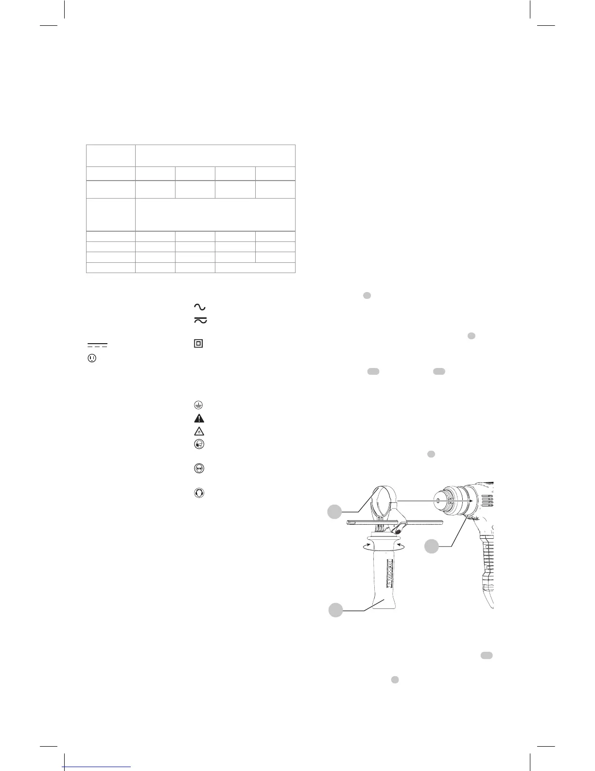
COMPONENTS (FIG. A)
WARNING: Never modify the power tool or any part
of it. Damage or personal injury couldresult.
Refer to Figure A at the beginning of this manual for a
complete list ofcomponents.
INTENDED USE
Your heavy-duty rotary hammers is designed for
professional concrete drilling and chiselingapplications.
DO NOT use under wet conditions or in presence of
flammable liquids orgases.
Your heavy-duty rotary hammer is a professional power
tools. DO NOT let children come into contact with the tool.
Supervision is required when inexperienced operators use
thistool.
ASSEMBLY AND ADJUSTMENTS
WARNING: To reduce the risk of serious personal
injury, turn unit off and disconnect it from
power source before making any adjustments or
removing/installing attachments or accessories.
An accidental start-up can causeinjury.
Side Handle and Depth Rod (Fig. B, C)
WARNING: To reduce the risk of personal injury,
ALWAYS operate the tool with the side handle
properly installed. Failure to do so may result in
the side handle slipping during tool operation and
subsequent loss of control. Hold tool with both hands
to maximizecontrol.
The side handle
5
clamps to the front of the gear case and
may be rotated 360˚ to permit right- or left-hand use.
Mounting the Straight Side Handle (Fig.B)
1. Widen the ring opening of the side handle
5
by
rotating it counterclockwise.
2. Slide the assembly onto the nose of the tool, placing
the steel ring
12
onto the collar
11
, past the bit holder
andsleeve.
3. Rotate the side handle assembly to the desired position.
For hammerdrilling horizontally with a heavy drill
bit, place the side handle assembly at an angle of
approximately 20° to the tool for optimumcontrol.
4. Lock the side handle mounting assembly in place by
securely tightening the handle
5
rotating it clockwise
so that the assembly will notrotate.
Fig. B
11
5
12
To Adjust the Depth Rod (Fig. C)
1. Push in and hold the depth rod release button
10
on
the sidehandle.
2. Move the depth rod
9
so the distance between the
end of the rod and the end of the bit equals the desired
drillingdepth.
 Loading...