13
ENGLISH
To actuate the fuel gauge, press and hold the fuel
gauge button(n). A combination of the three green
LED lights will illuminate designating the level of
charge left. When the level of charge in the battery
is below the usable limit, the fuel gauge will not
illuminate and the battery will need to berecharged.
NOTE: The fuel gauge is only an indication of the
charge left on the battery pack. It does not indicate
tool functionality and is subject to variation based
on product components, temperature and end-
userapplication.
Variable Speed Switch (fi g.1)
To turn the tool on, squeeze the trigger switch(a). To
turn the tool off, release the trigger switch. Your tool
is equipped with a brake. The tool holder will stop as
soon as the trigger switch is fullyreleased.
The variable speed trigger switch enables you to
select the best speed for a particular application.
The farther you squeeze the trigger switch, the faster
the tool will operate. For maximum tool life, use
variable speed only for starting holes orfasteners.
NOTE: Continuous use in variable speed range is
not recommended. It may damage the switch and
should beavoided.
Side Handle (fi g.1)
WARNING: To reduce the risk of
personal injury, ALWAYS operate
the tool with the side handle properly
installed. Failure to do so may result
in the side handle slipping during tool
operation and subsequent loss of
control. Hold tool with both hands to
maximizecontrol.
The side handle(e) clamps to the front of the gear
case and may be rotated 360˚ to permit right- or
left-hand use. The side handle must be tightened
sufficiently to resist the twisting action of the tool if
the accessory binds or stalls. Be sure to grip the
side handle at the far end to control the tool
during astall.
To loosen side handle, rotatecounterclockwise.
Forward/Reverse Control Button
(fi g.1, 2)
WARNING: Always wait until the motor
has come to a complete standstill
before changing the direction ofrotation.
A forward/reverse control button(b) determines
the direction of the tool and also serves as a lock
offbutton.
WARNING: No connection is to be
made to the earthterminal.
Follow the fitting instructions supplied with good
quality plugs. Recommended fuse: 3A.
Using an Extension Cable
An extension cord should not be used unless
absolutely necessary. Use an approved extension
cable suitable for the power input of your charger
(see Technical Data). The minimum conductor size
is 1 mm
2
; the maximum length is 30m.
When using a cable reel, always unwind the
cablecompletely.
ASSEMBLY AND ADJUSTMENTS
WARNING: Prior to assembly and
adjustment, always remove the battery
pack. Always switch off the tool before
inserting or removing the batterypack.
WARNING: Use only DEWALT battery
packs andchargers.
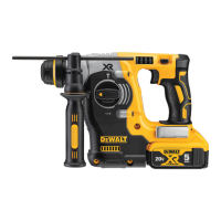
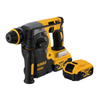
Inserting and Removing the
Battery Pack from the Tool (fi g.3)
WARNING: To reduce the risk of injury,
never depress the battery release button
without removing the battery pack.
Depressing the battery release button
without removing the battery pack
can result in the battery pack falling
outunexpectedly.
NOTE: For best results, make sure your battery
pack is fullycharged.
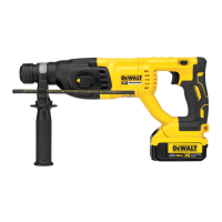
TO INSTALL THE BATTERY PACK INTO THE TOOL HANDLE
1. Align the battery pack(f) with the rails inside the
tool’s handle (fig.3).
2. Slide it into the handle until the battery pack is
firmly seated in the tool and ensure that it does
notdisengage.
TO REMOVE THE BATTERY PACK FROM THE TOOL
1. Press the battery release button(g) and firmly
pull the battery pack out of the toolhandle.
2. Insert battery pack into the charger as
described in the charger section of thismanual.
FUEL GAUGE BATTERY PACKS (FIG.3)
Some DEWALT battery packs include a fuel gauge
which consists of three green LED lights that indicate
the level of charge remaining in the batterypack.

 Loading...