ENGLISH
8
battery pack in a warm environment such as in a metal
shed or an uninsulatedtrailer.
3. If the battery pack does not charge properly:
a. Check operation of receptacle by plugging in a lamp
or other appliance;
b. Check to see if receptacle is connected to a light
switch which turns power off when you turn out the
lights;
c. Move the charger and battery pack to a location
where the surrounding air temperature is
approximately 65°F – 75°F (18° – 24°C);
d. If charging problems persist, take the tool, battery
pack and charger to your local servicecenter.
4. The battery pack should be recharged when it fails to
produce sufficient power on jobs which were easily
done previously. DO NOT CONTINUE to use under these
conditions. Follow the charging procedure. You may
also charge a partially used pack whenever you desire
with no adverse effect on the batterypack.
5. Foreign materials of a conductive nature such as, but
not limited to, grinding dust, metal chips, steel wool,
aluminum foil, or any buildup of metallic particles
should be kept away from charger cavities. Always
unplug the charger from the power supply when there
is no battery pack in the cavity. Unplug the charger
before attempting toclean.
6. Do not freeze or immerse the charger in water or any
otherliquid.
Storage Recommendations
1. The best storage place is one that is cool and dry, away
from direct sunlight and excess heat orcold.
2. For long storage, it is recommended to store a fully
charged battery pack in a cool dry place out of the
charger for optimalresults.
NOTE: Battery packs should not be stored completely
depleted of charge. The battery pack will need to be
recharged beforeuse.
SAVE THESE INSTRUCTIONS FOR
FUTURE USE
SPECIFICATIONS
DCH733 DCH773
Rated Size 1-7/8" (48 mm) 2" (52 mm)
Tool Holder SDS MAX SDS MAX
Voltage (DC) 60 V 60 V
Impact Energy in Joules (EPTA) 13.3 J 19.4 J
No-Load RPM 177–355 145–290
No-Load BPM 1350–2705 1105–2210
Optimum Drilling Range
3/4"–1-3/4"
(19 mm–45 mm)
7/8"–1-7/8"
(22 mm–48 mm)
Max. Diameter Core 5" (125 mm) 6" (150 mm)
Rotation Control
E-Clutch® E-Clutch®
SPECIFICATIONS
DCH733 DCH773
Weight 19 lbs (8.6 kg) 21 lbs (9.5 kg)
Length 23.5" (59.7 cm) 25.4" (64.5 cm)
Width 4.5" (11.3 cm) 4.5" (11.3 cm)
Height 11.2" (28.4 cm) 11.2" (28.4 cm)
Vibration Control
SHOCKS® SHOCKS®
Chipping Yes Yes
Variable Speed Dial Yes Yes
Variable Speed Dial Positions 7 7
Noise Values [dB(A)]
L
pA
(Emission Sound Pressure
Level)
97 96
L
WA
(Sound Power Level) 108 107
K (Uncertainty of Given Sound
Level)
3 3
Vibration Values (m/s
2
)
Drilling into Concrete (Value
a
h,HD
)
9.0 10.1
Uncertainty K 1.5 1.5
Chipping/Chiselling (Value
a
h,Cheq
)
8.8 9.4
Uncertainty K 1.5 1.5
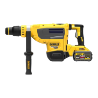
COMPONENTS (FIG. A)
WARNING: Never modify the power tool or any part
of it. Damage or personal injury couldresult.
Refer to Figure A at the beginning of this manual for a
complete list ofcomponents.
Intended Use
Your heavy-duty cordless rotary hammer is designed for
professional concrete drilling and chiselingapplications.
DO NOT use under wet conditions or in presence of
flammable liquids orgases.
Your heavy-duty cordless rotary hammer is a professional
powertool.
DO NOT let children come into contact with the tool.
Supervision is required when inexperienced operators use
thistool.
Trigger Switch (Fig. A)
To turn the tool on, squeeze the trigger switch
1
. To turn
the tool off, release the trigger switch. Your tool is equipped
with a brake. The chuck will stop as soon as the trigger
switch is fullyreleased.
Variable Speed Trigger Switch
The variable speed trigger switch enables you to select
the best speed for a particular application. The farther you
squeeze the trigger switch, the faster the tool will operate.
For maximum tool life, use variable speed only for starting
holes orfasteners.

 Loading...