ENGLISH
9
NOTE: Continuous use in variable speed range is not
recommended. It may damage the trigger switch and
should beavoided.
ASSEMBLY AND ADJUSTMENTS
WARNING: To reduce the risk of serious personal
injury, turn unit off and remove the battery pack
before making any adjustments or removing/
installing attachments or accessories. An
accidental start-up can causeinjury.
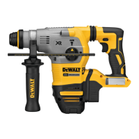
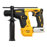
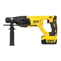
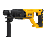
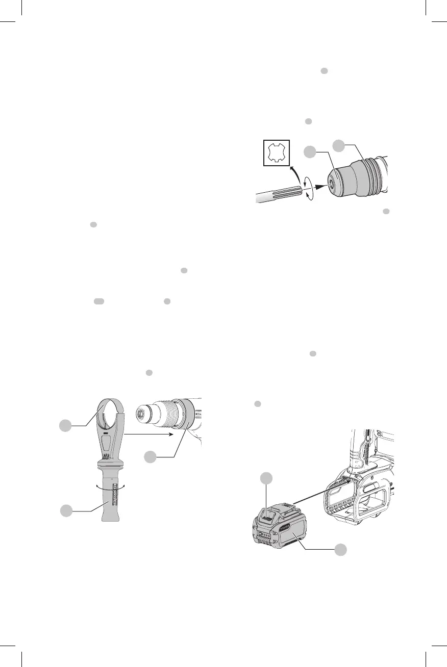
Side Handle (Fig. D)
WARNING: To reduce the risk of personal injury,
ALWAYS operate the tool with the side handle
properly installed. Failure to do so may result in
the side handle slipping during tool operation and
subsequent loss of control. Hold tool with both hands
to maximizecontrol.
The side handle
2
clamps to the front of the gear case and
may be rotated 360˚ to permit right- or left-hand use.
Mounting the Straight Side Handle
(Fig. D)
1. Widen the ring opening of the side handle
2
by
rotating it counterclockwise.
2. Slide the assembly onto the nose of the tool, through
the steel ring
13
and onto the collar
3
, past the chisel
holder andsleeve.
3. Rotate the side handle assembly to the desired position.
For hammerdrilling horizontally with a heavy drill
bit, place the side handle assembly at an angle of
approximately 20° to the tool for optimumcontrol.
4. Lock the side handle mounting assembly in place by
securely tightening the handle
2
rotating it clockwise
so that the assembly will notrotate.
Fig. D
3
2
13
Bit and Bit Holder
WARNING: Burn Hazard. ALWAYS wear gloves when
changing bits. Accessible metal parts on the tool and
bits may get extremely hot during operation. Small
bits of broken material may damage barehands.
The rotary hammer can be fitted with various chisel bits
depending on the desired application. Use sharp drill
bitsonly.
Inserting and Removing SDS MAX Bits
(Fig. E)
1. Insert bit in the bit holder
6
and apply downward
pressure while rotating to secure the bit into place. The
bit shank must beclean.
2. Ensure the bit is properlyengaged.
NOTE: The bit needs to move several centimeters in and
out of the bit holder
6
when properlyengaged.
6
7
Fig. E
3. To remove the bit, pull back the locking sleeve
7
and
pull the bitout.
OPERATION
WARNING: To reduce the risk of serious personal
injury, turn unit off and remove the battery pack
before making any adjustments or removing/
installing attachments or accessories. An
accidental start-up can causeinjury.
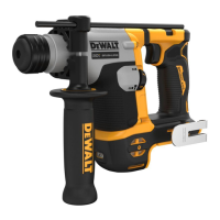
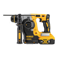
Installing and Removing the Battery Pack
(Fig. F)
NOTE: For best results, make sure your battery pack is
fullycharged.
To install the battery pack
8
into the tool’s battery cage,
align the battery pack with the rails inside the tool’s battery
cage and slide it in until the battery pack is firmly seated.
Ensure that it does notdisengage.
To remove the battery pack from the tool, press the release
button
9
and firmly pull the battery pack out of the tool
handle. Insert it into the charger as described in the charger
section of thismanual.
Fig. F
8
9
Proper Hand Position (Fig. G)
WARNING: To reduce the risk of serious personal injury,
ALWAYS use proper hand position as shown.
 Loading...