6
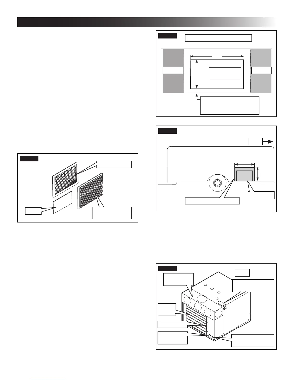
FIG. 2
14″
20″
StorageStorage
Inside Cabinet Front Cutout
Opening For
Front Grille
1″ Required Above Floor
Line For Attaching Front
Grille With Screws
FIG. 3
Rear
22-3/4″
15″
Floor Line
Outside Wall Opening
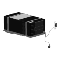
3. Remove the unit from its carton. Inspect for ship-
ping damage.
4. Locate the discharge air plenum on the unit. Cut
the required hole or holes for your installation.
The 3 front holes for direct discharge, or the side
and/or top holes for ducted applications. See
(FIG. 4).
FIG. 4
120 Vac Junction
Box Connection
Rear
Discharge
Plenum
Return
Air
Data Plate
Thermostat
Connection
12 Vdc & Furnace
Connection
A. Choosing Proper Location For Unit
1. The RV manufacturer engineering staff should
carefully review each oor plan to determine the
best location before starting an installation.
Alternate congurations and methods
may be used which still allow the unit to
operate properly; however, these alter-
nate congurations and methods MUST
be approved by Dometic Corporation.
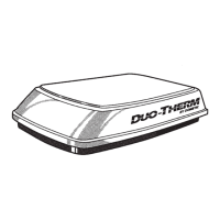
B. Grilles And Registers
The following accessories are available in various kits to
simplify installations. See (FIG. 1).
1. Indoor direct discharge grille alone, with indoor
vents.
2. Indoor direct or ducted discharge grille with out-
door grille.
3. Indoor direct discharge grille with outdoor grille
and outdoor rain shield.
FIG. 1
Inside Grille
(Ducted Shown)
Filter
Outside Grille
C. Opening Preparation
1. FIRE OR ELECTRICAL SHOCK
HAZARD. Verify there are no obstacles inside
RV’s roof and/or walls (wires, pipes, etc.). Shut
OFF gas supply, disconnect 120 Vac power from
RV, and disconnect positive (+) 12 Vdc terminal
from supply battery BEFORE drilling or cutting
into RV. Failure to obey these warnings could
result in death or serious injury.
2. Once the oor plan has been reviewed and the
compartment has been selected for unit installa-
tion, a 22-3/4″ wide by 15″ high opening through
the sidewall or outside panel is required. The in-
terior compartment must be at least 20″ deep.
See (FIG. 2) & (FIG. 3).
INSTALLATION INSTRUCTIONS