9
INSTALLATON INSTRUCTIONS
● Red/White wire to the 12V+ terminal
● Black wire to the 12V– terminal
● Orange wire to the "COMMS" terminal
6. Inspect all connections to make sure they are
tight and not touching any other terminals or
wires.
7. Push the wires back through the base into the
wall. Place cover on the thermostat and push
until an audible click is heard.
8. This completes the unit installation.
I. System Checkout
1. Verify that all features of the system work. See
the LCD SZ thermostat Operating Instructions
or User’s Guide. Reconnect the 12Vdc and 120
Vac power supplies. Check fan speeds, cooling
mode, heating mode, and furnace mode (if con-
nected) operation.
If features do not work, disconnect the 120 Vac
and 12 Vdc power supplies and verify that all
wiring is correct.
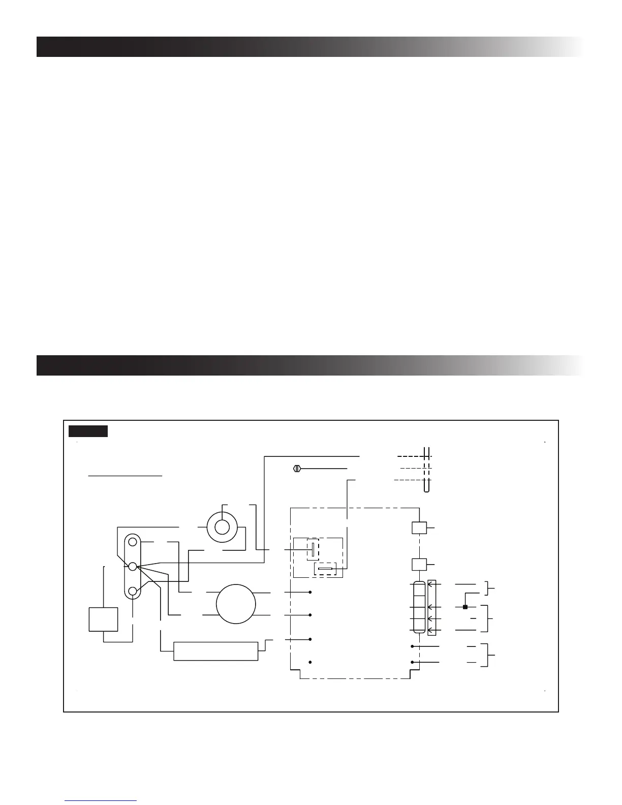
WIRING DIAGRAM
A. Unit Wiring Diagram - Earlier Version
%/.
%/.
72)851$&(
,)86('
72
767$7
9
6833/<
-
3$66('',(/(&75,&
5(':+7
-
37&5
237
%/8
5('
2/
&
5
6
287'225
7(03
6(1625
02725
12
&20
<
<
<
%/8
%/.
5('
<
.5(/$<
)5((=(
6(1625
-
9$&
86(&233(5
+=2
&21'8&7256
21/<
*51<(/($57+
:+71(87
%/./,1(
767$79
9
%/8:+7
%/8:+7
<
<
&200
25*
%/.
5('
9
)851$&(
)851$&(
%/.
5(9(56,1*9$/9(
%5
:+7
:+7
%5
5('
:+7
FIG. 7
 Loading...