7
EN
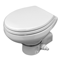
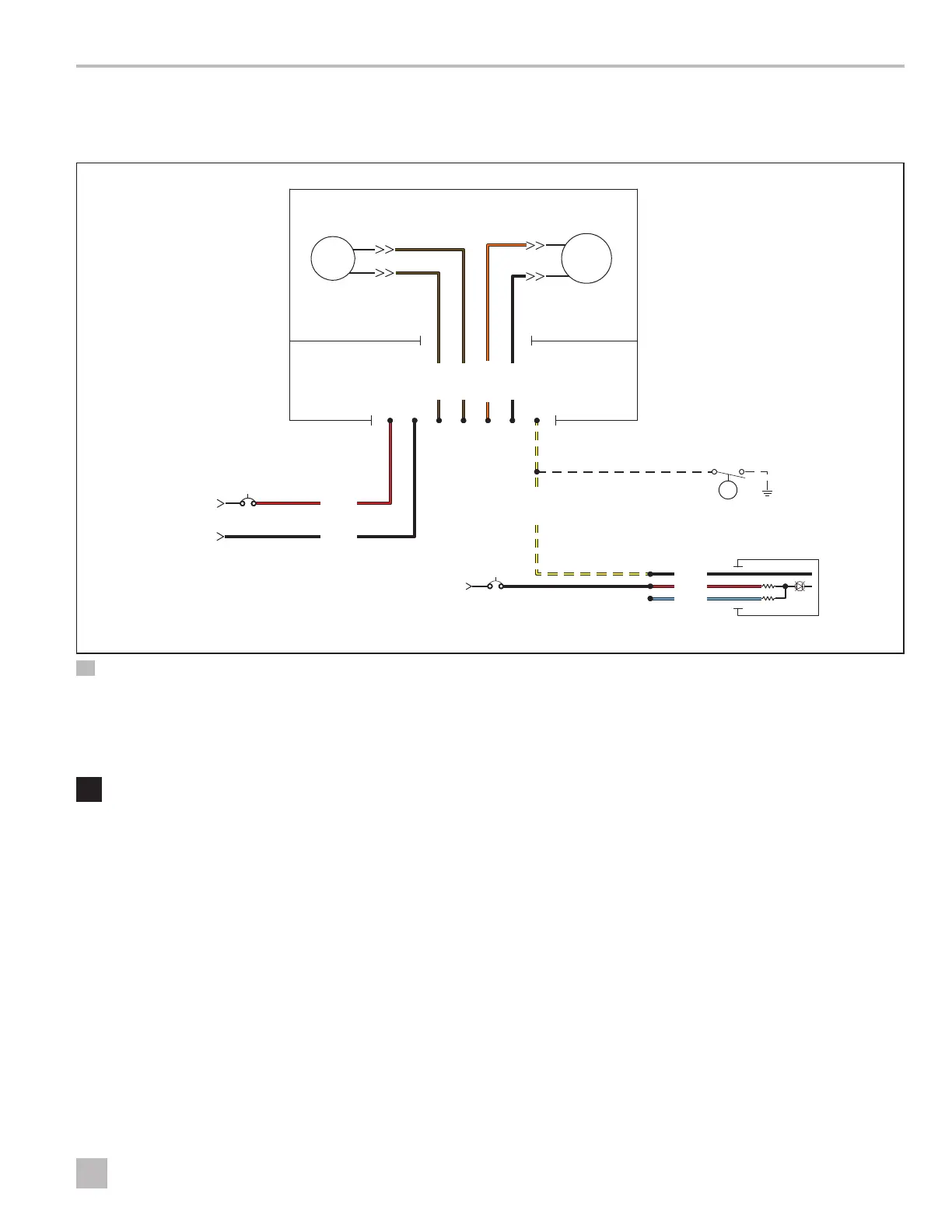
MasterFlush 7600 Series Toilet Wiring Diagram
5 Wiring Diagram
This section provides the MasterFlush wiring diagram.
Water Valve
Circuit Board
with Internal Fuse
Motor
Full Tank Float
OPTIONAL (recommended)
DTM01 Panel Option
+12 VDC Input
Input Power Supply -12 VDC
+12 VDC Input
- VDC Input
Fuse or Breaker
0.5 AMP
Fuse or Breaker
25 AMP
Toilet
Brown
Brown
Orange
Black
Black
Red
Yellow
1 2 7
3 4 5 6
Black
Red
Blue
5 Wiring Diagram
6 Installation
WARNING: ELECTRICAL SHOCK HAZARD.
Turn the power off before performing any electrical
installation or maintenance work. Failure to obey
this warning could result in death or serious injury.
NOTICE: Do not install the toilet in a shower. Be sure
to follow the recommended installation requirements in
“Specifications” on page5.
NOTICE: Be sure the foot pedal, when depressed, will
touch the same flat surface as the installed toilet.
NOTICE: Do not over-tighten the floor mounting nuts.
To prevent any distortion of the base, alternate between
sides when tightening.
NOTICE: When reconnecting the water supply line, do
not over tighten.
This section describes the toilet preparation, removal,
and installation processes.
6.1 Preparing to Install the Toilet
1. Verify the location meets all the recommended
clearances for the new model. See Figure3 &
Figure4.
2. Turn off the power to the toilet’s location.
3. Turn off the water supply to the toilet’s location.
6.2 Removing an Existing Toilet
I
If a toilet removal is unnecessary, skip to “Installing
the Toilet” on page8.
1. Disconnect the power to the toilet.
 Loading...