(b)
12
Volts d.c.
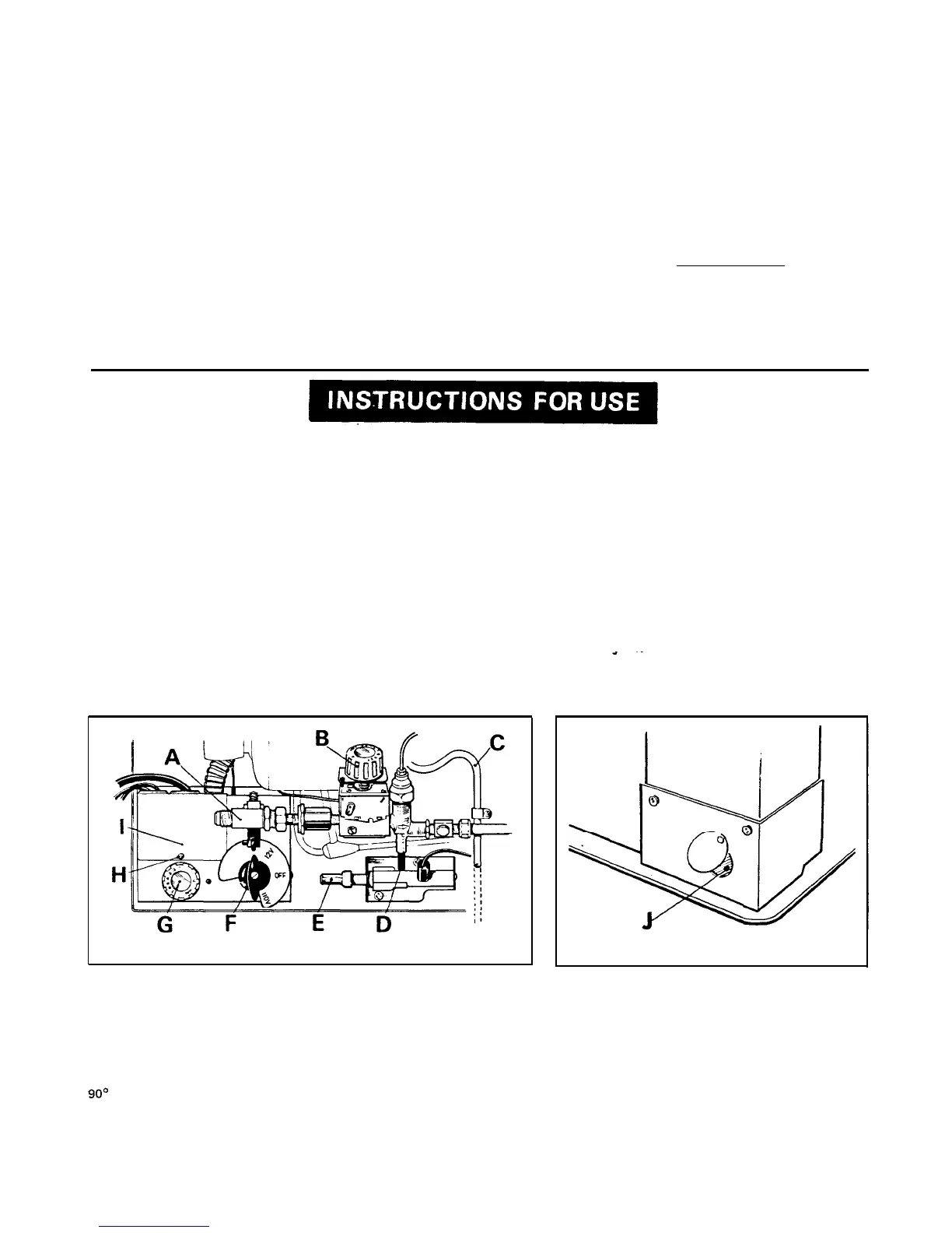
At the back of the refrigerator, at the lower left-hand corner, is the
electric equipment control box (1, fig. 4). Take off the cover from the
box by removing the screw
(H),
and the terminal block will be
visible.
The two terminals at the left-hand end of the terminal block are
the 12 volt supply connections. From these, the refrigerator must be
connected to the main battery in the vehicle by means of two wires,
passing through the entry opening (temporarily sealed with a
dust-
cap)
in the top of the box. Polarity is not important, but the body or
chassis of the automobile or trailer should not be
used
as a substitute
for one of the wires.
The current is 8 amps when the refrigerator is operating on 12 volts
therefore the wiring from the battery to the refrigerator must be
heavy enough to carry this load satisfactorily without voltage drop.
The minimum size of wiring to be used is 14 A.W.G.
The connections to the battery should be made using ring type
clamps with tightening bolts to ensure good contact with the battery
poles.
To prevent the refrigerator operating and draining the battery
when the engine is switched off, it is recommended that an automatic
cut-out relay is installed between the battery and the refrigerator so
that the refrigerator will not draw current from the battery when the
ignition is switched off.
Do not connect lights or any other electrical components to the
wiring from the battery to the refrigerator.
(c)
Fuse
Inside the control box (1, fig.4). in an insulated holder. is a 10 amp
fuse, which is to protect the 12 volt circuit in the event of a short.
If the fuse burns out, trace the cause and correct it before fitting a
similar type 10 amp fuse and reconnecting.
8. DEFROST WATER DRAIN PIPE
The metal pipe
(C,
fig.4) at the back’of the refrigerator is for defrost
water disposal. When installing, connect a suitable length of rubber or
plastic tubing to this pipe, passing the free end through the floor to the
outside of the trailer. The tubing must slope downwards all the way and
must not be pinched or kinked.
9. TESTING AND STARTING UP
When the installation is complete, check all gas connections and fittings
on the refrigerator for tightness in case they have loosened during ship
ping. After lighting the burner
(see
item 11). all gas connections
should-be checked for leaks by applying a soap/water solution over
them and watching for bubbles. Do not use a flame. Thereafter, all
connections should be checked at least once a month. The refrigerator
gas equipment must not be subjected to an internal pressure exceeding
22 inches of water column.
See that the trailer is level in both directions then check that the
ice-tray shelf in the top of the frozen food storage compartment is also
level, from side to side and from front to back, by means of a small
bubble level placed on the ice-tray shelf. This is important for satis-
factory operation of the cooling unit.
10. LEVELING
In the boiler of the cooling unit, ammonia vapor is distilled from an
ammoniawater mixture and carried to the finned condenser where it
liquifies.
The liquid flows to the evaporator inside the cabinet where it
creates cold by evaporating into a circulating flow of hydrogen gas. If
the evaporator is not level, the liquid may accumulate forming pockets
which can impair the gas circulation, or block it completely, in which
case cooling will stop.
When the trailer is stationary for a period, it must be level so that
the refrigerator can operate properly. When the trailer is being parked,
therefore, the level should be checked, preferably by means of a small
bubble level placed on the ice-tray shelf, and the position of the bubble
observed. If necessary, the level of the trailer should then be adjusted
so that the
icetray
shelf is level from side to side, and from front to
back.
When the trailer is on tow, the continuous rolling and pitching
movement will not normally affect the operation of the refrigerator,
but when the trailer is parked for more than a short period, the sensi-
tivity of the refrigerator should be remembered.
(iii)
Push in the blue plunger (D) of the flame failure device for 10
to 15 seconds to clear air from fhe pipe-line.
(When
starting
initially, or after changing a gas bottle, it may be necessary to
depress the plunger for a minute or longer to clear all the air
from the pipes). Still pressing in the plunger (D), push in the
button
(E)
of the piezo igniter. The burner should light, but
continue to press in the plunger (D) for a further 15 seconds
then release it end check that the burner is alight by looking at
the flame through the
opening
(J).
If the burner has not lit.
repeat the lighting procedure:
The ice-tray shelf should show signs of cooling after about an
hour.
Note: If the gas has to be re-lit when the ice-making compart-
ment is still cold, the thermostat dial (B) must first be
turned to MAX and returned to its normal setting only
after the burner is alight.
The
refrigerator
has a flame failure device which will
FIG. 4
11. STARTING THE REFRIGERATOR
The gas and electric controls are located at the rear of the refrigerator
and are accessible through the lower ventilator in the wall of the
vehicle. The gas shutoff valve and the electric voltage-change switch
are interlocked so that both methods of operation cannot be inad-
vertently
used
at the same time.
The lower ventilator is removed by turning the handle of its catch
90’
counter-clockwise, then pulling it out.
(a)
L.P.
Gas
Operation
-
Lighting the burner (See figs. 4
&
5)
(i) Check that the voltage change switch
(F)
is at the ‘off’ position,
then turn on the gas valve (A).
(ii)
Turn the gas thermostat knob
(B)
to setting No. 4.
automatically shut off the gas to the burner if the flame is
blown out. While the blue plunger
(D)
is being held in,
this device is temporarily inoperative.
FIG. 5
(b)
Electric Operation
-
(See
fig.4)
The refrigerator can be operated on 12 volts d.c. or 110 volts
a.c.
provided the voltagechange switch (F) is set at the appro-
priate position.
To start the refrigerator on electric operation:-
(i)
Turn off the gas valve
(A),
-
its handle will then be pointing
away from the back of the cabinet.
(ii)
Turn the voltage change switch (F) to the required setting, then
connect the refrigerator to the appropriate voltage supply.
When the electrical supply cord is connected to a
1
10 volt
a.c.
supply. the voltage on the switch
(F)
should show
110V;
when
connected to the battery, the voltage on the switch
(F)
should
show 12V.
(iii) Turn the electric thermostat knob
(G)
to No. 4. The ice-tray
shelf should show signs of cooling after about an hour.
4

 Loading...