11
SECTION 5 DC COMPONENTS
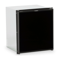
5.1 DC Heating Element
Remove the heater leads from the lower circuit board or
relay and measure for proper resistance across the two
leads. You should obtain the following readings ± 10%:
NOTE: The DC mode is a holding mode not a full cooling
mode. DC should be used once the unit is cooled down on
gas or AC and driving (constant supply of DC) down the
road. A continuity reading will indicate an open or com-
plete circuit. Never over or under size the DC heater.
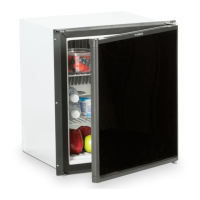
5.2 Thermistor
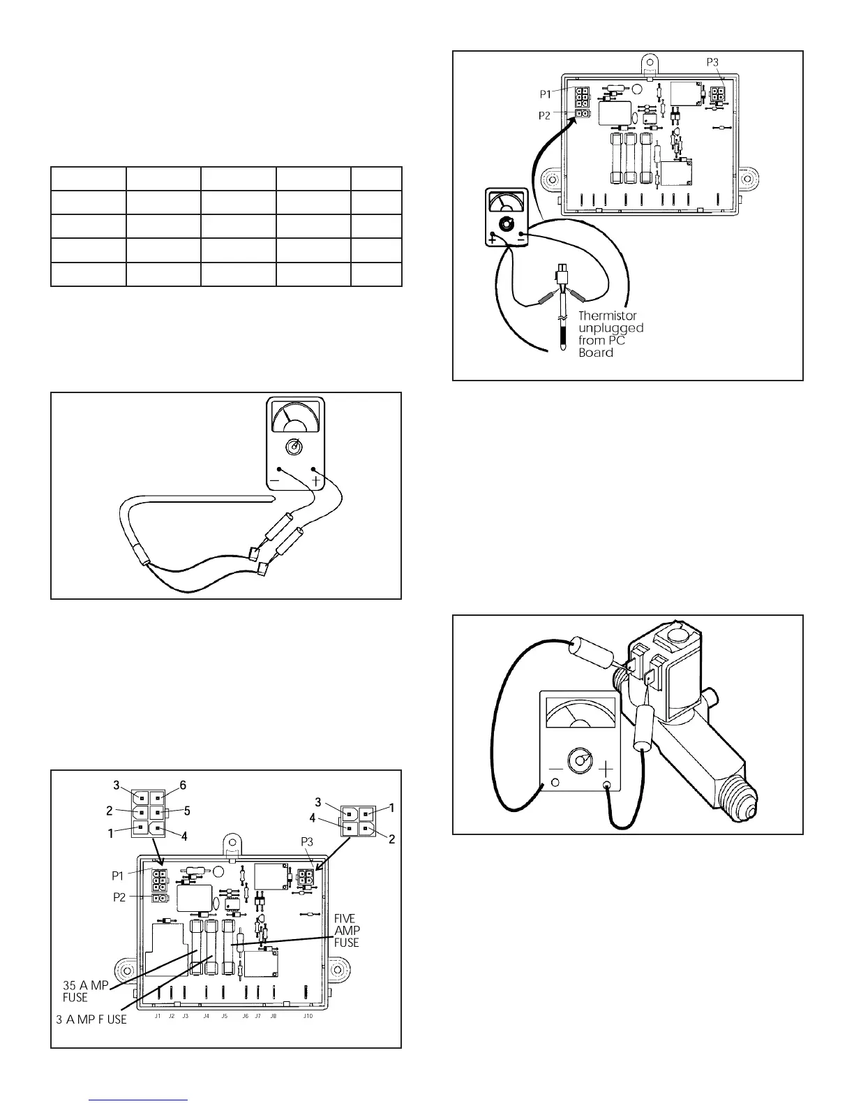
Disconnect the thermistor harness from the P2, 2-pin ter-
minal on the lower circuit board. Place the thermistor in
a glass of ice water (more ice than water), approximately
33° F to 35° F. Wait 8 to 10 minutes. You should get a
reading of approximately 8,000 to 10,000 ohms. Always
test from the wire side as shown with the meter as not to
create a connection problem at the P2 connector.
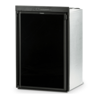
5.3 Solenoid Valve
Check the solenoid coil with a properly calibrated ohm
meter. Remove the connectors from the solenoid and
measure the resistance across the terminals. The proper
reading would be 49 ohms with tolerance range of ten
percent. Failure of the solenoid is very unlikely. Next,
hook up a manometer at the test port. Then check for DC
volts at gas valve terminals (Yellow + White -) while the
unit is in trial-for-ignition. If DC volts are present and pres-
sure is low, replace the valve. If DC volts are not present
at the valve while the unit is in trial-for-ignition, verify that
the wire at Plug 3, Terminal 2 on lower circuit board has
DC volts (9 or more).
5.4 Igniter
The igniter used on Dometic model refrigerators operates
on 12 volt DC. On gas operation the igniter senses the
resistance through the ame between the electrode and
burner. When there is no ame at the burner, the resis-
tance is high and the igniter begins sparking to light the
burner. As soon as the ame is lit, the resistance between
the electrode and burner drops and the igniter stops
sparking. The resistance is monitored by the igniter, and,
if for any reason the ame goes out, the igniter begins
sparking until the burner is lit. The resistance between the
electrode and burner drops and the igniter stops spark-
ing.
Model Watts Amps Volts Ohms
RM2354 150 12.5 12 .96
RM2454 175 15.0 12 .80
RM2554 175 15.0 12 .80
RM2663 215 18.0 12 .67
 Loading...