13
Wires from control board P3 harness to relay.
Terminal 85 P3-3 harness blue negative.
Terminal 86 P3-4 harness blue positive.
Wires to relay from DC source and DC heater.
Terminal 87 to DC heater positive.
Terminal 30 positive from DC power source.
If DC voltage to terminals 85 & 86, but no continuity be-
tween 30 & 87 the relay will need to be changed. Refer to
wiring diagram on the back of the product or check parts
list for proper diagram. To acquire the proper wiring dia-
gram always use the product number.
5.8 Upper Circuit Board
With main ON/OFF switch on display panel in OFF
position: Check for DC voltage at Plug 1, Terminal 4
(orange wire +) positive and terminal 5 (red wire -)
negative DC on the lower circuit board. If no voltage,
then check fuse condition. Check for DC voltage be-
tween J4 positive and J10 negative terminals on the
lower circuit board (rst generation) or J1 positive and
J10 negative on the current board (3850415013). If
no voltage on orange wire, fuse test OK and voltage
into lower control, replace the lower board. Next,
with main ON/OFF switch on check for DC voltage at
the upper circuit board between terminal 4 (orange
wire) and terminal 3 (red wire) which is negative (–)
DC. If no voltage and your previous check veried
voltage at the lower circuit board between the wires,
test and/or replace the cable assembly between the
upper and lower controls.
Upper Board Pin Connector Wire Location
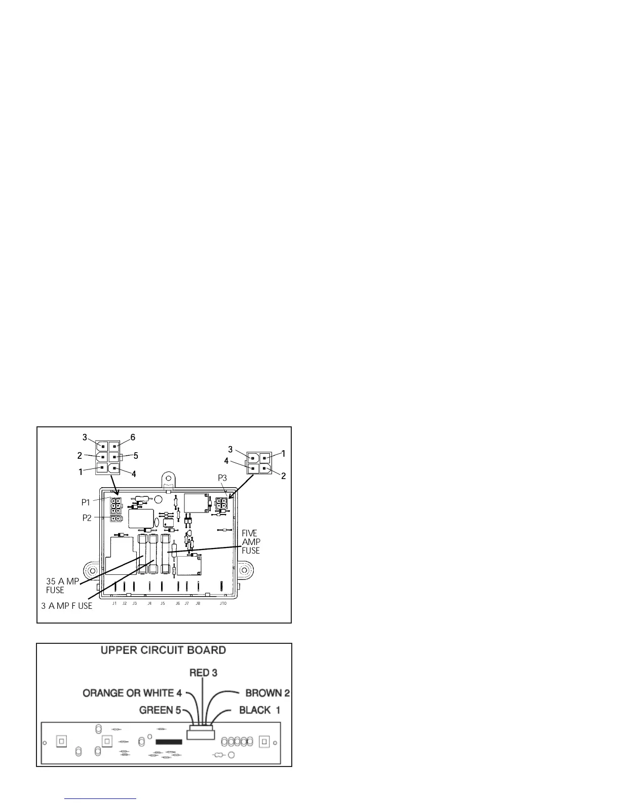
5.9 Lower Circuit Board
P1 To upper control board
P2 Thermistor
P3 To gas valve, igniter
J1 To DC heater
J2 To interior light and climate control
J3 Negative lead from thermocouple
J4 Positive 12V DC from terminal block
J5 AC line voltage (Black)
J6 AC neutral line (White)
J7 AC neutral out to AC heater
J8 AC line out to AC heater Switched side
J10 Positive lead from thermocouple
Thermocouple positive lead may be on the ground strip
on early units. Reference full wiring diagram next page.
WIRING Original style control 3 way & 2 way
Note: 2 Way will not have a J1 for DC heater
P1 To upper control board
P2 Thermistor
P3 To gas valve, igniter and DC heater relay if 3 way
J1 Positive 12V DC from terminal block
J2 To interior light and climate control.
J3 To auxiliary fan (S.) and/or ice maker heat tape
J4 Negative lead from thermocouple
J5 AC line voltage (Black)
J6 AC neutral line (White)
J7 AC neutral out to AC heater
J8 AC line out to AC heater Switched side
J9 Positive wire from thermocouple
J10 Negative to Chassis ground
Note: Terminals 9 and 10 could be reversed as both termi-
nals are ground on control board.
WIRING: Current style control 3/2 way, 2 way
will not have wires from P3 to external DC relay
Board part number 3850415013
WIRING: Current style with integrated igniter
Board part number 3850712013
P1 To upper control board
P2 Thermistor
P3 To gas valve
J2 To interior light / climate control.
J4 Positive 12V DC from terminal block
J5 AC line voltage (black)
J6 AC neutral line (white)
J7 AC neutral out to AC heater
J8 AC line out to AC heater Switched side
J10 Negative to Chassis ground
Note: Units that have integrated igniter do not use a
thermocouple.
 Loading...