Control Cavity 9–2
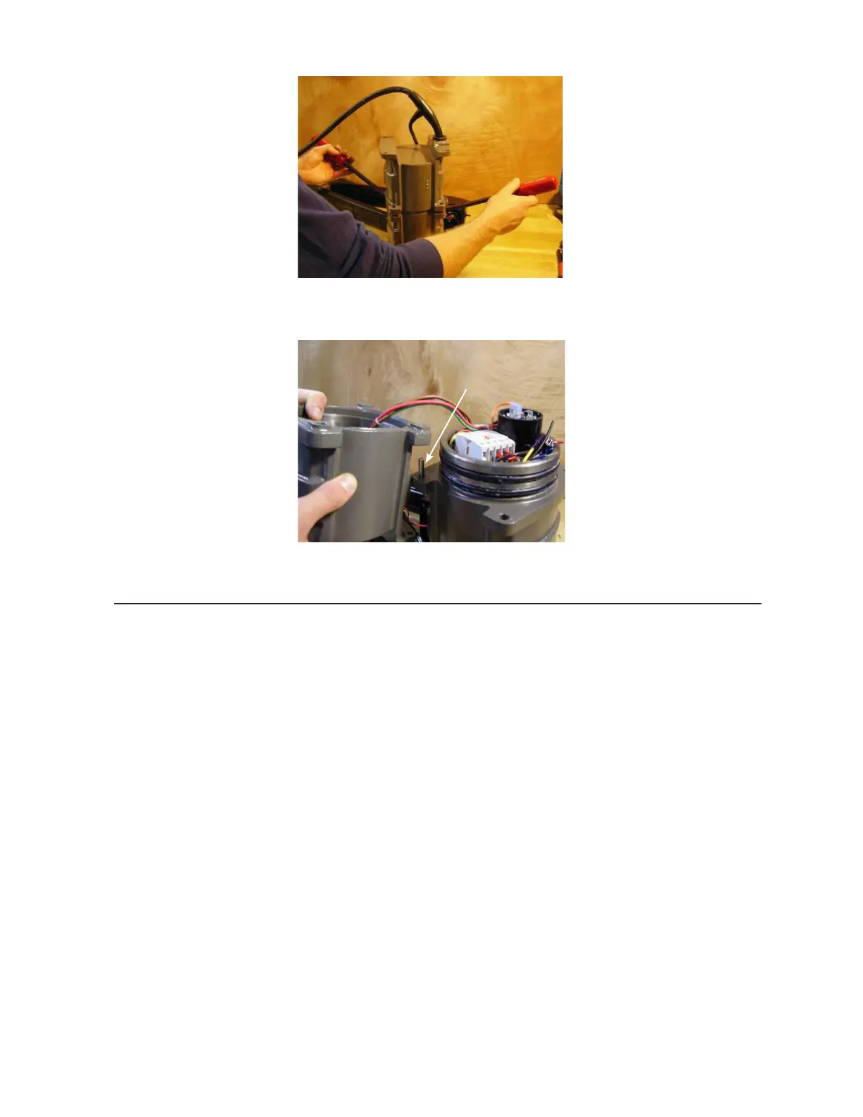
7. Hang the control housing on the motor housing by inverting it and hanging it on the
guide pin.
Motor Contactor and Controls
Inspect the internal components for signs of corrosion, moisture and/or damage. The motor
contactor has 10 screw-type terminals that hold leads:
• Terminals A1 and A2 are the coil
• Terminals 1/L1, 3/L2, and 5/L3 are the line side of the contacts
• Terminals 2/T1, 4/T2 and 6/T3 are the load side of the contacts
When the on/off switch or manual run energizes the coil, the contacts close and run the pump.
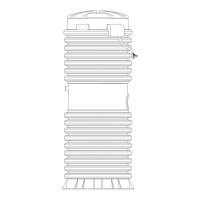
To test motor contactor operation:
1. With the power off, verify that the control bracket is wired correctly and is seated
properly into the motor housing.
2. Check the continuity across 1/L1 and 2/T1; across 3/L2 and 4/T2; and 5/L3 and 6/T3.
If they read “closed” (000 or short), replace the contactor. If they read “open” (1 or
OL), proceed.
3. Connect a jumper wire from A2 (coil) to 1/L1 (contact).
4. Plug the pump into a power source. Check nameplate for proper voltage.
5. Turn the power on. The contactor should engage and transfer L1 power to the
motor. If the pump does not run, check the voltage across the contacts, the start
components and the motor windings.
Figure 9-4
Figure 9-3
 Loading...