Installation procedure
CBC-8000 capacitor bank control installation and operation instructions MN916001EN—October 2018 Eaton.com 25
14 Wire harness
The CBC-CTRLSEN14P-40 wiring harness is used with the
control’s 14-pin DIN connector. This wiring harness includes
mating connector MS3106F20-27S.
The DIN pin assignments and wire colors are associated as
follows:
DIN pin Wire color
ABlack
BWhite
C Green
DRed
E Red and White Stripe
F Yellow and White Stripe
G Orange and White Stripe
H Brown
I Black and White Stripe
J Brown and White Stripe
KYellow
L—
MBlue
N—
Socket mount installation
Perform the following steps install the control into a meter
socket:
1. If necessary, remove the old control from the socket.
2. Verify that the meter socket is wired correctly for the
style of control that is being installed. For more
information about mounting styles, see Ta bl e 5 on
page 21 and the following figures.
3. Line up the bottom blades of the control with the socket
jaws of the meter socket.
4. Gently push the bottom blades of the control into the
socket.
5. Gently rock the top blades of the control into place.
6. Secure the control to the meter socket with a sealing
ring.
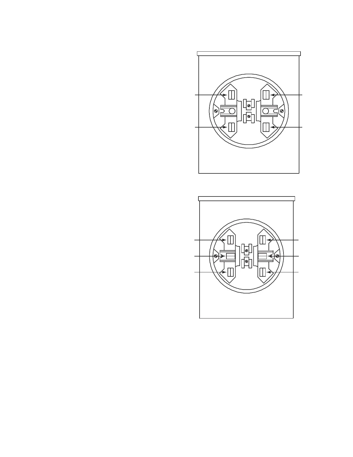
Figure 27. Four-jaw meter socket.
Figure 28. Six-jaw meter socket.
7. Install an earth grounding wire from the grounding lug,
located on the bottom of the control, to the earth
following standard industry practices.
The ground resistance should be less than 20 ohms
when complete. The grounding wire should be 16 gauge
or larger.
The recommended best practice is to install a grounding
wire from the CBC grounding lug, located on the bottom
of the control, to a common ground point at the top of
the capacitor bank rack. A separate or independent
grounding wire must run from the capacitor bank rack to
the earth following standard industry practices.
2
4
1
3
1
5
3
2
6
4
 Loading...


