CL-7 control in Siemens Corporation control
box
Table 3. Kit parts identification
Item Description Part Number Qty
1 CL-7 PRA wiring harness,
Siemens/Howard control
A64316200F 1
2 Faceplate, Right E0003X00G29 1
3 Left Hinge Bracket E0003X00G32 1
4 Siemens Retro Kit Magnet
Assembly
57A643282002 1
5 Hinge 0800071097Z 2
6 Machine Screw: 6-32x0.38 0800071090Z 6
7 Lock Washer: #6 SS 0800070916Z 4
8 Lock Nut: 6-32 0800071115Z 2
9 Ground Lead E0003X00G160 1
10 Adhesive cable-tie anchors 0800069825Z 2
11 Cable tie 0800011079Z 2
Required tools
Screwdriver (standard)
Screwdriver (Phillips head)
5/16-Inch nut driver or combination wrench
3/8-Inch nut driver or combination wrench
ote:N Verify all kit items are present before beginning
installation procedure.
Installation procedure
Follow these instructions to install the CL-7 PRA on a
voltage regulator manufactured by Siemens Corporation.
1. Remove existing control per manufacturer‘s
requirements. Retain the terminal block wing-nuts.
ote:N If the Siemens Corporation style wiring harness
(Figure 16), hinge and magnet assemblies
(Figure 18) have already been installed on the
control, proceed to Step 14.
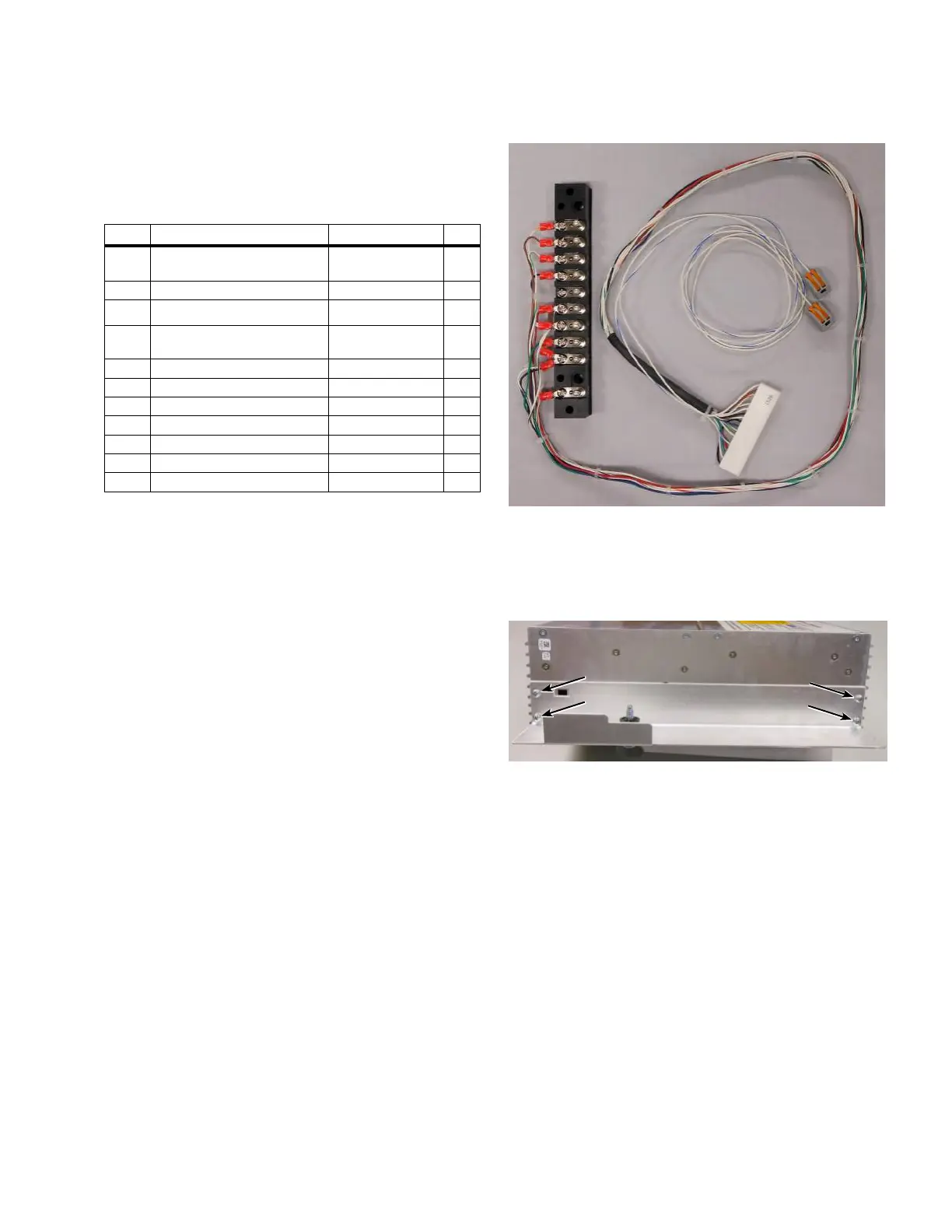
ote:N The Siemens harness may be equipped with
two wires colored white and white/blue with
two-terminal connectors as shown in Figure 16. The
wires are for connection to the CL-7 control general
purpose inputs (GPIs). The wires can be used for
analog voltage reduction or other programmable
functionality. See document MN225003EN, CL-7
Voltage Regulator Control Installation, Operation, and
Maintenance Instructions for more information on
the GPIs.
Figure 16. Siemens Corporation wiring harness for the
CL-7 control (Item 1)
2. Using a screwdriver, remove the four screws to
uninstall the existing latch bracket from the left side of
the CL-7 control; retain the screws. See Figure 17.
Figure 17. Removal of latch bracket from CL-7 control
3. Install the left hinge bracket (Item3) using the screws
retained from the last step. See Figure 18.
4. Install the hinges (Item5) using the provided screws
and washers (Items6 and 7). See Figure 18.
7
CL-7 Control Panel Retrofit
InstallatIon InstructIons MN225018EN April 2018
 Loading...


