CL-7 control in Eaton control box, dead front
Table 1. Kit parts identification
Item Description Part Number Qty
1 Jumper, 7 terminals width A613078004 1
2 Backpanel tool, plastic* A613098002 1
*Retain for future use.
ote:N Eaton‘s Universal PRA kit may include parts not
required for every installation. Only parts required for
this installation are included in this list.
Required tools
Screwdriver (Phillips)
Backpanel tool (included in kit)
ote:N Verify all kit items are present before beginning
installation procedure.
Installation procedure
Follow these instructions to install the CL-7 control in a
control box on an Eaton‘s Cooper Power series voltage
regulator with a dead-front backpanel.
1. Remove the existing control:
Refer to the appropriate voltage regulator control
manual for complete instructions on removing a
control.
Refer to document MN225016EN, VR-32 Voltage
Regulators CL-6 Series Control Installation, Operation,
and Maintenance Instructions for information on the
Eaton‘s Cooper Power series CL-6 series voltage
regulator control.
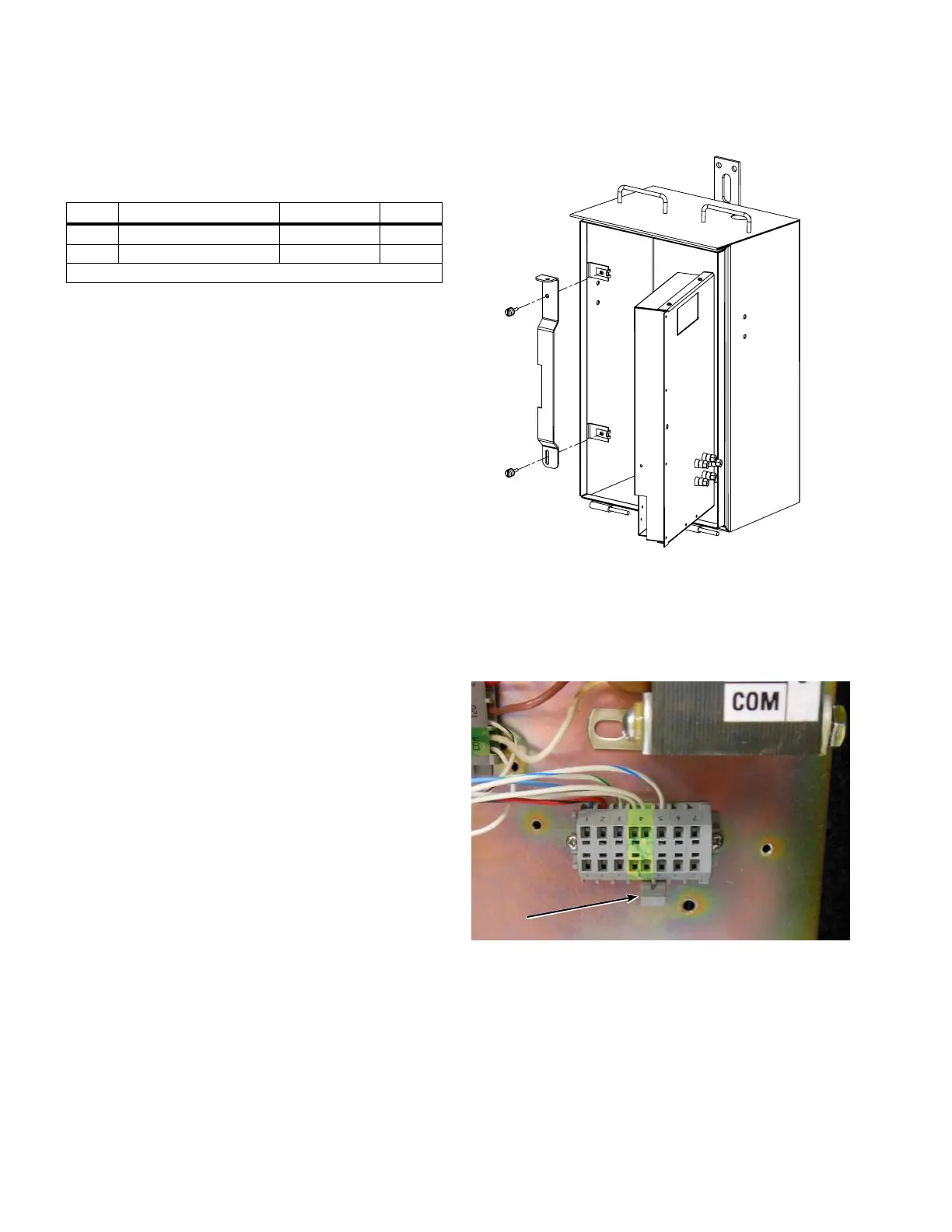
2. For control boxes with an existing CL-6B regulator
control, use a screwdriver to remove the latching
bracket from the control box mounting tabs. Refer to
Figure 1.
Figure 1. Control box bracket removal
3. In control boxes with a full back panel, locate the
TB8 terminal board and use the back panel tool to
remove the jumper between terminal 4 and 5. Refer
to Figure 2. This step is not required for the short back
panel.
Figure 2. Removing jumper from TB8
4. Identify the terminal board containing the control plug
receptacle on the lower back panel. Peel back the strip
containing the terminal markings in the center of this
terminal board using the back-panel tool to reveal the
terminal board jumpers. See Figure 3.
2
CL-7 Control Panel Retrofit
InstallatIon InstructIons MN225018EN April 2018
 Loading...


