CL-7 control in General Electric control box
with fork-type terminal
Table 4. Kit parts identification
Item Description Part Number Qty
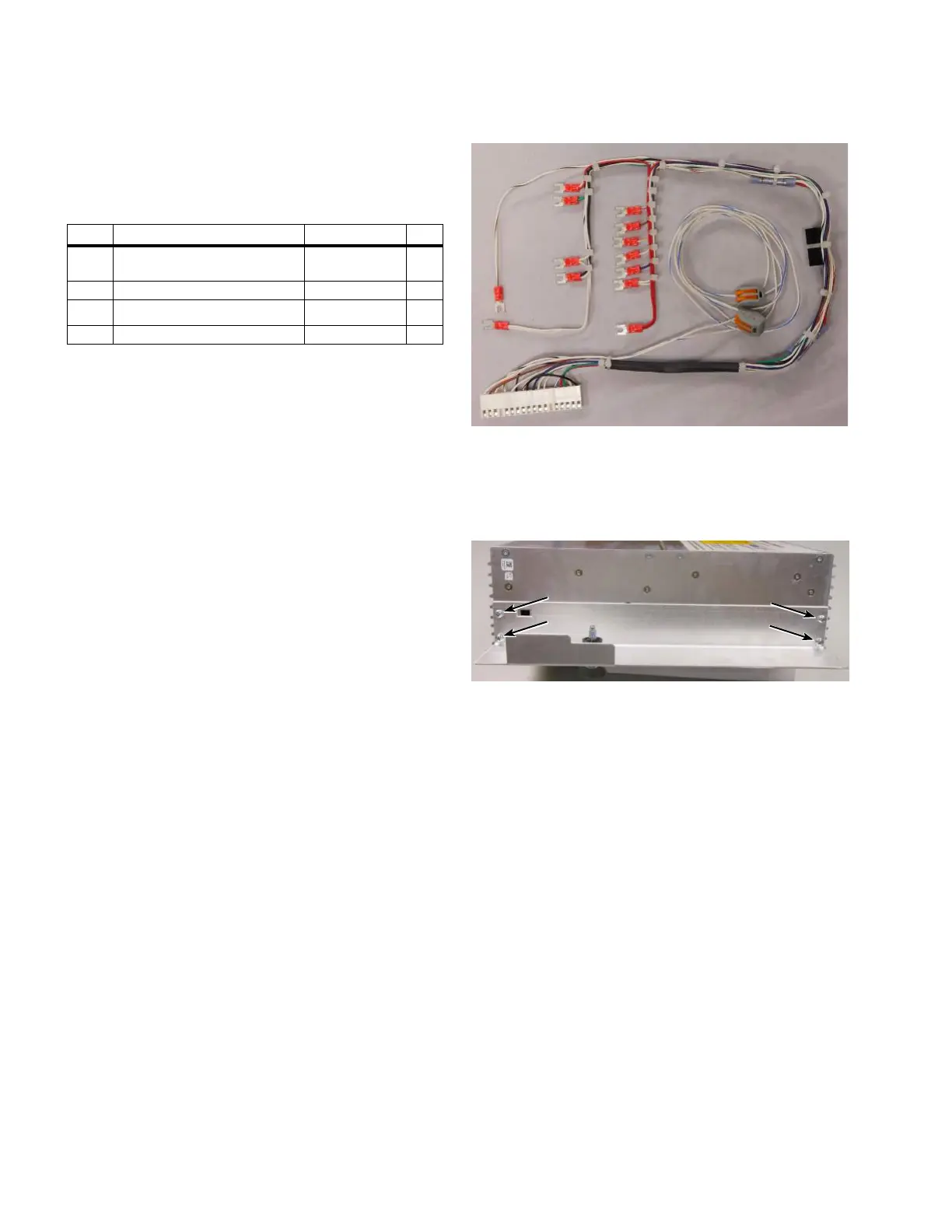
1 CL-7 PRA wiring harness,
General Electric fork-type terminal
A64316200G 1
2 Hinge bracket assembly E0003X00G22 1
3 Left side bracket E0003X00G25 1
4 Self adjusting latch E0003X00G158 1
Required tools
Screwdriver (standard)
Screwdriver (Phillips head)
3/8-Inch nut driver or combination wrench
ote:N Verify all kit items are present before beginning
installation procedure.
Installation procedure
Follow these instructions to install the CL-7 PRA on a
voltage regulator manufactured by General Electric with
fork-type terminal connections.
1. Remove existing control per the manufacturer‘s
requirements. Retain the hinge pins.
ote:N If the General Electric wiring harness (Figure 26),
hinge bracket and latch bracket (Figure 28) have
already been installed on the new CL-7 control,
proceed to Step 11.
ote:N The GE harness may be equipped with two wires
colored white and white/blue with two-terminal
connectors as shown in Figure 26. The wires
are for connection to the CL-7 control general
purpose inputs (GPIs). The wires can be used for
analog voltage reduction or other programmable
functionality. See document MN225003EN, CL-7
Voltage Regulator Control Installation, Operation, and
Maintenance Instructions for more information on
the GPIs.
Figure 26. Item 1, General Electric fork-terminal wire
harness
2. Using a screwdriver, remove the four screws to
uninstall the existing latch bracket from the left side of
the CL-7 control; retain the screws. See Figure 27.
Figure 27. Removal of latch bracket from CL-7 control
3. Install the General Electric latch bracket (Item3) on the
left side of the control using the screws retained from
the last step. See Figure 28.
10
CL-7 Control Panel Retrofit
InstallatIon InstructIons MN225018EN April 2018
 Loading...


