UPS System Installation
4-8 Eaton 93E UPS (300/400 kVA, 380/400/415V) Installation and Operation Manual
4.6.2 Installing Parallel Pull Chain and CAN Control Wiring and Connections
To install wiring:
1. Verify the UPS system is turned off and all power sources are removed. See Chapter 6, “UPS Operating
Instructions,“ for shutdown instructions.
2. Installing Parallel system, see Figure 4-6.
3. To locate the appropriate terminals and review the wiring and termination requirements, see
paragraph 3.2.3, Table 4-2, Figure 4-3 and Figure 4-5.
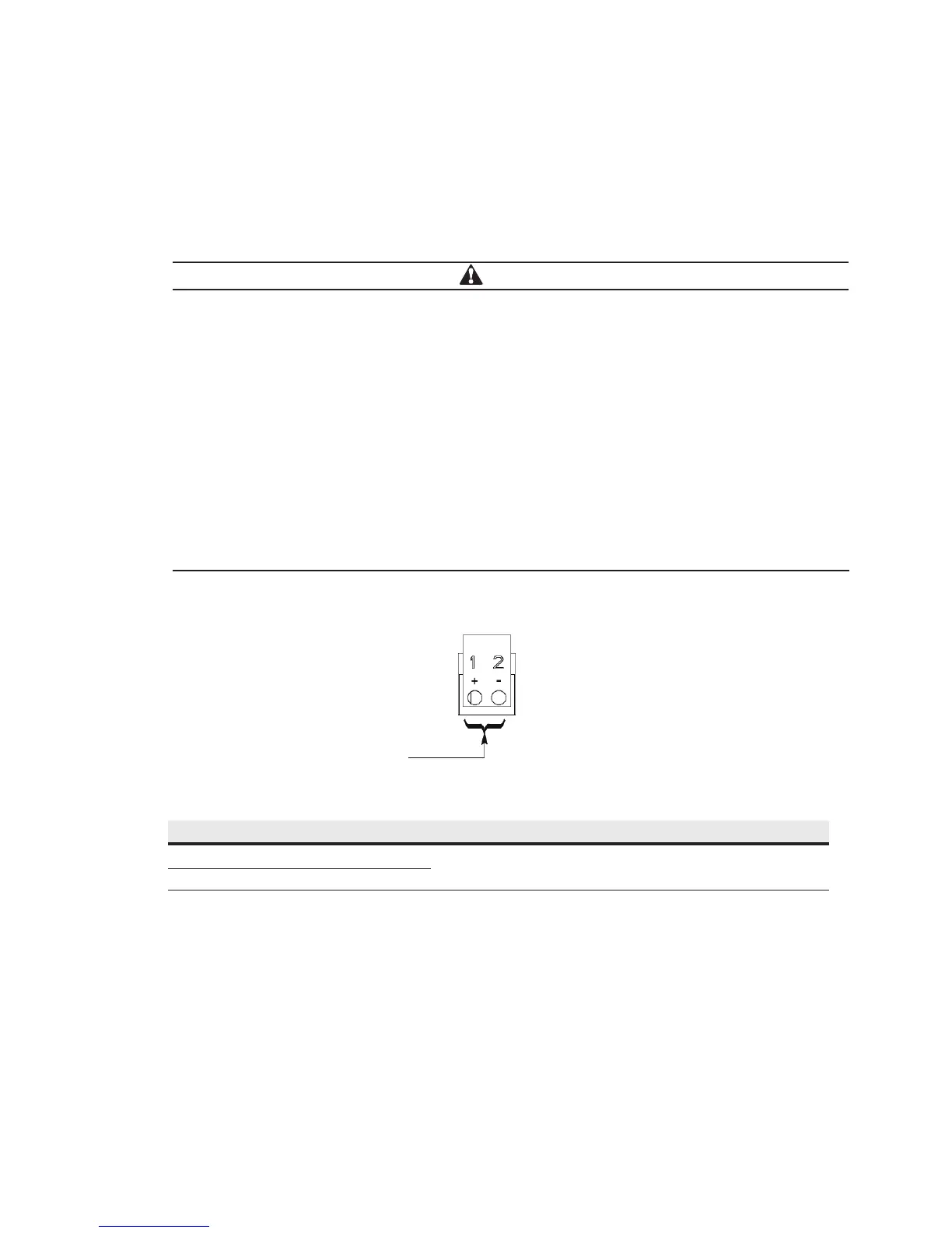
Figure 4-5. Pull Chain Terminal Block Connector Assignments
Table 4-2. Pull Chain Connections
Pull Chain Terminal Name Description
1 Pull Chain +
Output: Backup control for parallel operation.
2 Pull Chain –
4. Remove the small parts from the knockout in the right side plate.
Pull Chain
5. Route and install cables between the UPS cabinets through their own connected holes(connected hole 1
and connected hole 2) that are use for parallel cables routing.
6. Route and install pull chain wiring (Twisted Wires 0.5-2.0mm
2
) between the UPS cabinets and cabinet
MOBs. See Figure 4-3, and Figure 4-6for wiring information.
CAUTION
• Parallel system combined input and output wiring length should be in accordance with the
following rule. It should be designed to ensure that wiring impedance from point of supply to
load connection for each UPS module in a multi-module system is equal, or within a tolerance of
approximately ±10%. This is to ensure approximately equal current sharing when in static
bypass mode.
Total length of 1A + 1B = Total length of 2A + 2B
= Total length of 3A + 3B
= Total length of 4A + 4B
• If installing only two UPS modules (redundant), this requirement is no longer required as each
UPS is capable of supporting the full bypass requirement. However, this would preclude future
expansion.
• Ensure that each UPS static bypass is fed from a single common source, as is an external
bypass switch if installed. If each UPS is fed with a separate rectifier source, please consult
Eaton for advice on compatibility.
 Loading...


