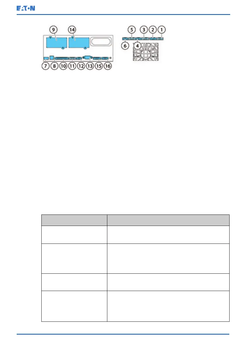
Figure 27: Communication interfaces in the 30/40 kW frame
1. TB11, not used
2. TB10, not used
3. TB9, not used
4. TB8, external CAN
termination
5. TB7, external CAN
6. TB6, pull chain bus
7. USB1, USB host (connection
to accessories)
8. USB2, USB device (connec-
tion to computer)
9. MiniSlot 1
10. TB1, signal input 1-5
11. TB2, not used
12. TB3, not used
13. Serial COM port RS-232
14. MiniSlot 2
15. TB4, EPO
16. TB5, relay output
See Figure 26: Communication interfaces in the 15/20 kW standard and C-model
frames and Figure 27: Communication interfaces in the 30/40 kW frame for the
location of communication interfaces in 91PS/93PS UPS.
6.2 Native signal terminals
Table 23: Native signal terminals
Terminal
Pins
TB6 Pull chain Pin 1: EXT Pull chain return
Pin 2: External pull chain
TB7 External CAN
connection
Pin 1: CAN cable shield grounding
Pin 2: CAN GND
Pin 3: CANBL
Pin 4: CANBH
TB8 CAN termination jumper Pin 1: CAN termination 1
Pin 2: CAN termination 2
TB1 Customer alarm, input Pin 1: Signal input 5 return
Pin 2: Signal input 5
Pin 3: Signal input 4 return
Pin 4: Signal input 4
© Eaton Corporation plc 2020. All rights reserved. Revision: 006 Document ID: P-164000493 78 (126)
Eaton 91PS/93PS UPS 8–40 kW User’s and Installation Guide
 Loading...


