Effective 10/2004
Page 10
I.L. 70C1036H05
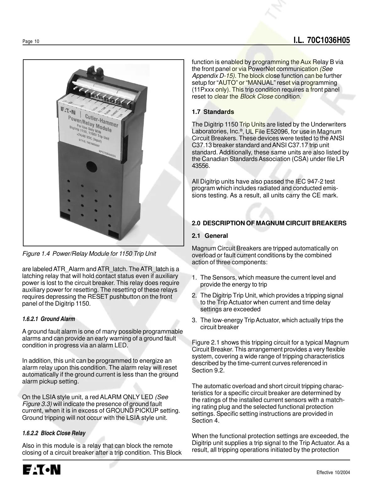
Figure 1.4 Power/Relay Module for 1150 Trip Unit
are labeled ATR_Alarm and ATR_latch. The ATR_latch is a
latching relay that will hold contact status even if auxiliary
power is lost to the circuit breaker. This relay does require
auxiliary power for resetting. The resetting of these relays
requires depressing the RESET pushbutton on the front
panel of the Digitrip 1150.
1.6.2.1 Ground Alarm
A ground fault alarm is one of many possible programmable
alarms and can provide an early warning of a ground fault
condition in progress via an alarm LED.
In addition, this unit can be programmed to energize an
alarm relay upon this condition. The alarm relay will reset
automatically if the ground current is less than the ground
alarm pickup setting.
On the LSIA style unit, a red ALARM ONLY LED (See
Figure 3.3) will indicate the presence of ground fault
current, when it is in excess of GROUND PICKUP setting.
Ground tripping will not occur with the LSIA style unit.
1.6.2.2 Block Close Relay
Also in this module is a relay that can block the remote
closing of a circuit breaker after a trip condition. This Block
function is enabled by programming the Aux Relay B via
the front panel or via PowerNet communication (See
Appendix D-15). The block close function can be further
setup for “AUTO” or “MANUAL” reset via programming
(11Pxxx only). This trip condition requires a front panel
reset to clear the Block Close condition.
1.7 Standards
The Digitrip 1150 Trip Units are listed by the Underwriters
Laboratories, Inc.
®
, UL File E52096, for use in Magnum
Circuit Breakers. These devices were tested to the ANSI
C37.13 breaker standard and ANSI C37.17 trip unit
standard. Additionally, these same units are also listed by
the Canadian Standards Association (CSA) under file LR
43556.
All Digitrip units have also passed the IEC 947-2 test
program which includes radiated and conducted emis-
sions testing. As a result, all units carry the CE mark.
2.0 DESCRIPTION OF MAGNUM CIRCUIT BREAKERS
2.1 General
Magnum Circuit Breakers are tripped automatically on
overload or fault current conditions by the combined
action of three components:
1. The Sensors, which measure the current level and
provide the energy to trip
2. The Digitrip Trip Unit, which provides a tripping signal
to the Trip Actuator when current and time delay
settings are exceeded
3. The low-energy Trip Actuator, which actually trips the
circuit breaker
Figure 2.1 shows this tripping circuit for a typical Magnum
Circuit Breaker. This arrangement provides a very flexible
system, covering a wide range of tripping characteristics
described by the time-current curves referenced in
Section 9.2.
The automatic overload and short circuit tripping charac-
teristics for a specific circuit breaker are determined by
the ratings of the installed current sensors with a match-
ing rating plug and the selected functional protection
settings. Specific setting instructions are provided in
Section 4.
When the functional protection settings are exceeded, the
Digitrip unit supplies a trip signal to the Trip Actuator. As a
result, all tripping operations initiated by the protection
Courtesy of NationalSwitchgear.com
 Loading...