Effective 6/01
I.B. ATS-RM05
Page 9
4.4 POWER CABLE CONNECTION
POWER CONDUCTORS MAY HAVE VOLTAGE PRE-
SENT THAT CAN CAUSE SEVERE PERSONAL
INJURY OR DEATH. DE-ENERGIZE ALL POWER OR
CONTROL CIRCUIT CONDUCTORS TO BE CON-
NECTED TO THE TRANSFER SWITCH EQUIPMENT
BEFORE BEGINNING TO WORK WITH THE CON-
DUCTORS AND/OR TERMINATING THEM TO THE
EQUIPMENT.
USE CABLE LUGS, NOT DESIGNED FOR THE
TRANSFER SWITCH MAY CAUSE HEATING PROB-
LEMS. BREAKER LUGS ONLY MOUNT TO THE
BREAKER, WHILE TRANSFER SWITCH LUGS
MOUNT TO BOTH THE BREAKER AND THE BUS-
BAR BEHIND THE BREAKER. FOR INSTALLATION
INSTRUCTIONS, REFER TO THE INSTRUCTION
LEAFLET SUPPLIED FOR THE SPECIFIC LUGS.
TO HELP PREVENT COMPONENT DAMAGE OR
FUTURE MALFUNCTIONS, USE EXTREME CARE TO
KEEP CONTAMINANTS OUT OF THE TRANSFER
SWITCH EQUIPMENT WHEN MAKING POWER
CABLE CONNECTIONS.
Test all power cables prior to connection to the unit to
ensure that conductors or cable insulation has not been
damaged while being pulled into position.
Power cables are to be connected to solderless screw
type lugs located on the transfer switch switching
devices. Verify that the lugs supplied will accommodate
the power cables being used. Also verify that the cables
comply with local electrical codes. Standard transfer
switch equipment, as supplied from the factory, will
accommodate the wire sizes shown in Table 4.1.
Carefully strip insulation from the power cables to avoid
nicking or ringing of the conductor strands. Prepare the
stripped conductor termination end by cleaning it with a
wire brush. If aluminum conductors are used, apply an
appropriate joint compound to the clean conductor sur-
face area.
Transfer Switch Number of
Amp Rating Wire Size Range Cables per Phase
30 - 100 #14 - 3/0 1
150 - 200 #6-300MCM 1
Table 4.1 Wire Size for Automatic Transfer Switch
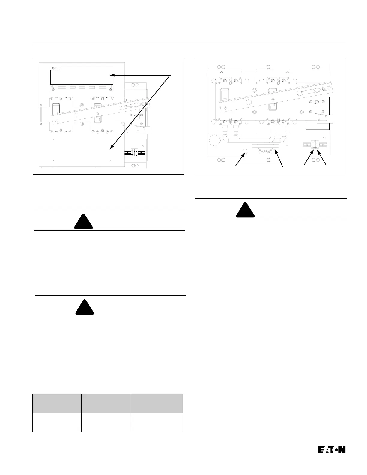
Figure 4-4 Deadfront Removal
Figure 4-5 Cable Connections
Ground Screw
51
52
Neutral
E1
E2
N1
N2
T1
T2
 Loading...