Page 2
the normal power source, again depending upon the
type of transfer equipment being used (Figure 1-1).
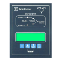
In automatic transfer switch equipment, the switch’s
intelligence system initiates the transfer when normal
power fails or falls below a preset voltage. If the emer-
gency power source is a standby generator, the transfer
switch initiates generator starting and transfers to the
emergency power source when sufficient generator volt-
age is available. When normal power is restored, the
transfer switch automatically transfers back and initiates
engine shutdown. In the event the normal power source
fails and the emergency power source does not appear,
the automatic transfer switch remains connected to the
normal power source until the emergency power source
does appear. Conversely, if connected to the emer-
gency power source and the emergency power source
fails while the normal power source is still unavailable,
the automatic transfer switch remains connected to the
emergency power source.
Automatic transfer switches automatically perform the
transfer function, and include three basic elements:
(1) Main contacts to connect and disconnect the load
to and from the source of power.
(2) A mechanism to make the transfer of the main con-
tacts from source to source.
(3) Intelligence/supervisory circuits to constantly moni-
tor the condition of the power sources and thus pro-
vide the intelligence necessary for the switch and
related circuit operation.
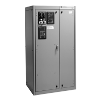
1.2.1 DESIGN CONFIGURATION
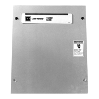
The Cutler-Hammer transfer switch is a rugged, com-
pact design that utilizes molded case switches to trans-
fer essential loads from one power source to another
(Figure 1-2). Molded case switches are interlocked to
prevent both switches from being closed at the same
time.
1.3 TRANSFER SWITCH CATALOG NUMBER
IDENTIFICATION
Transfer switch equipment catalog numbers provide a
significant amount of relevant information pertaining to a
specific piece of equipment. The Catalog Number
Identification Table (Table 1.1) provides the required
interpretation information. An example is offered to ini-
tially simplify the process.
Example: Catalog Number (circled numbers correspond
to position headings in Table 1.1)
The catalog number RTHMFDA20100WSU describes
an automatic transfer switch with the switching devices
mounted horizontally in the enclosure. The intelligence
I.B. ATS-RM05
Effective 6/01
Positions 1-2 Position 3 Position 4 Positions 5-6
Basic Switching Device Control Switching
Device Orientation Panel Device
Residential RT Horizontal H Microprocessor M HFD Cutler-Hammer Series C FD
Position 7 Position 8 Positions 9-12 Position 13 Position 14 Position 15
Switching Device Number Ampere Voltage/
Arrangement of Poles Rating Frequency Enclosure Listing
Fixed Mount Molded Case A Two 2 30A – 0030 240VAC/60Hz W NEMA 1 S UL Listed U
Switches 70A – 0070 208VAC/60Hz B NEMA 3R R
100A – 0100
150A – 0150
200A – 0200
Table 1.1
Transfer Switch Catalog Number Explanation
➀
to
➁➂ ➃ ➄
to
➅➆ ➇ ➈
to
➉
RT H M FD A 2 0100 W S U
12 13
14
15
 Loading...