3 Commissioning
3.2 Table showing which status LED states correspond to which set rated operational currents
Elektronischer Motorstarter EMS/Electronic Motor Starter EMS 04/15 MN03407009Z-DE/EN www.eaton.com 49
3.2 Table showing which status LED states correspond to which set rated operational currents
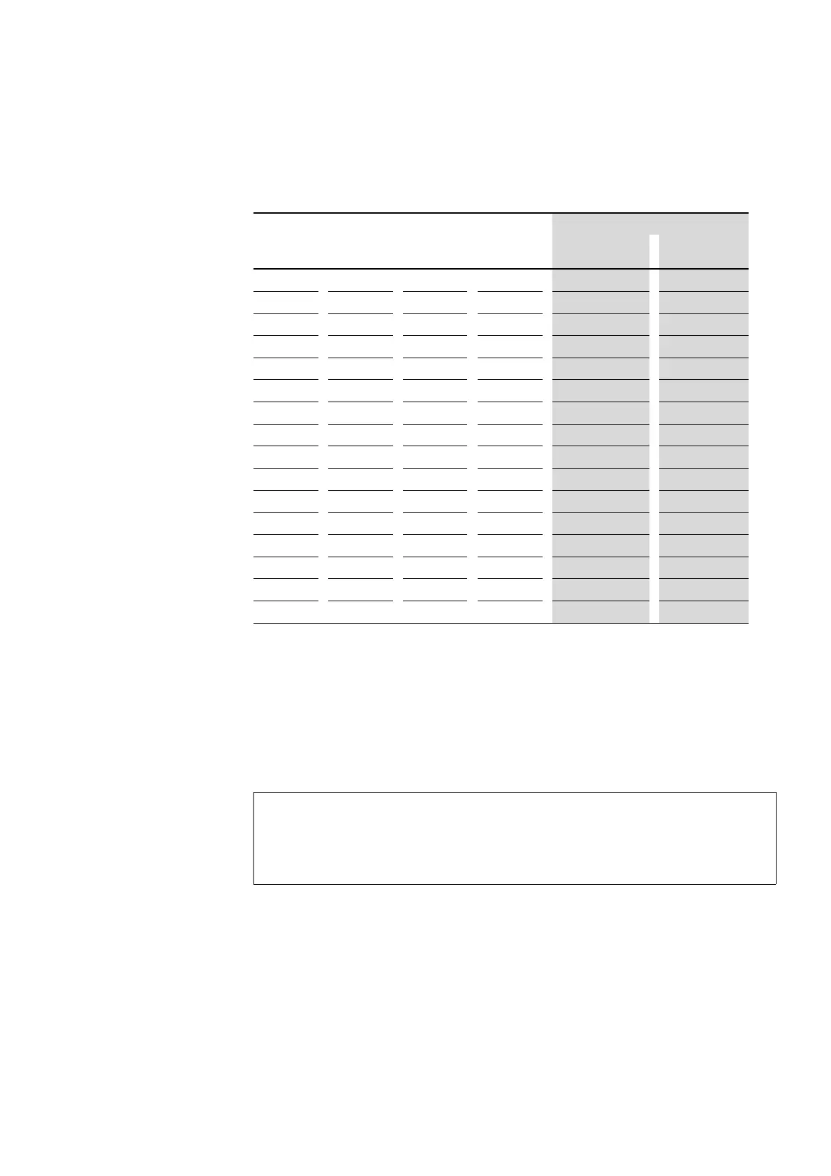
Table 6: Status LEDs and set rated operational current
3.3 Motor with brake
If a motor with a brake (connection to motor terminal board) is connected,
the 400 V AC brake must be connected to terminals 2/T1 and 6/T3.
A 230 V AC brake must be connected to terminal 4/T2 and to the motor‘s
neutral.
External brakes are actuated using separate contactor relays (e.g., DILA).
LED code Rated operational current [mA]
PWR R/ON L/- ERR EMS-…-2,4-… EMS-…-9-…
0 0 0 0 180 1500
0 0 0 1 250 2000
0
0 1 0 410 2500
0 0 1 1 560 3000
0 1 0 0 710 3500
0
1 0 1 870 4000
0
1 1 0 1020 4500
0 1 1 1 1170 5000
1 0 0 0 1330 5500
1 0 0 1 1480 6000
1 0 1 0 1630 6500
1 0 1 1 1790 7000
1 1 0 0 1940 7500
1 1 0 1 2090 8000
1
1 1 0 2250 8500
1 1 1 1 2400 9000
CAUTION
Make sure to add the brake‘s rated operational current to the
motor current monitoring value.
Configure the setting accordingly on the EMS motor starter!
 Loading...