3 Operating and indication elements
ESR5-NO-21-24VAC-DC 12/19 MN049007EN www.eaton.com 7
3 Operating and indication elements
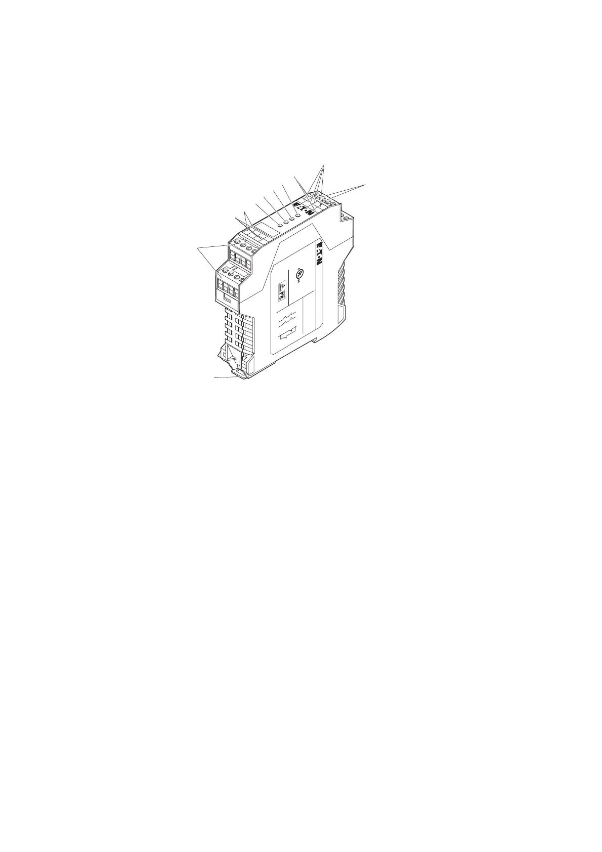
Figure 1: ESR5-NO-21-24VAC-DC
a Metal lock for mounting on the DIN rail
b COMBICON plug-in screw terminal blocks
c 13/14, 23/24 - undelayed enabling current paths
d 31/32-signaling current path
e LED status indicator, green - K2
f LED status indicator, green - K1
g LED status indicator, green - IN1/2
h LED status indicator, green - Power
i A1, A2 - supply voltage connection
j S11, S12, S21, S22 - input circuits
k S33, S34 - start circuit (activating circuit)
A
P
PRO
V
A
LS
1
3
2
3
3
1
14
2
4
3
2
ESR5-NO-21-24VAC-DC
31 13
14
32 23
24
A
1
S34
S
3
3 S11
S12
S2
1 S22
A
2
Power
IN 1/2
K
1
K2
LISTED
IND. CONT. EQ .
32FB
30 - 12 AW G
5 - 7 lbs-in s
Input: 24V ac/d c
Output: 240V ac/24V
dc.
B300 Pilotdut y
R300 Pilotdut y
ESR5-NO-21
-24VAC-DC
①
②
③
⑪
⑩
⑨
⑧
⑦
⑥
⑤
④

 Loading...


