Sectionalizing loadbreak switch
Eaton’s Cooper Power series sectionalizing loadbreak
switch rotates 360° in either direction for alternate source
selection. An externally-installed index plate prevents
rotation to positions other than the one desired. The
switch cannot be switched more than one position without
resetting the index plate.
A spring-loaded activating mechanism ensures quick
loadbreak action and positive contact engagement through
all positions. Switching can be accomplished in less than
one cycle, and should be performed with a hotstick. To
follow are operation examples for the two most common
sectionalizing switch configurations.
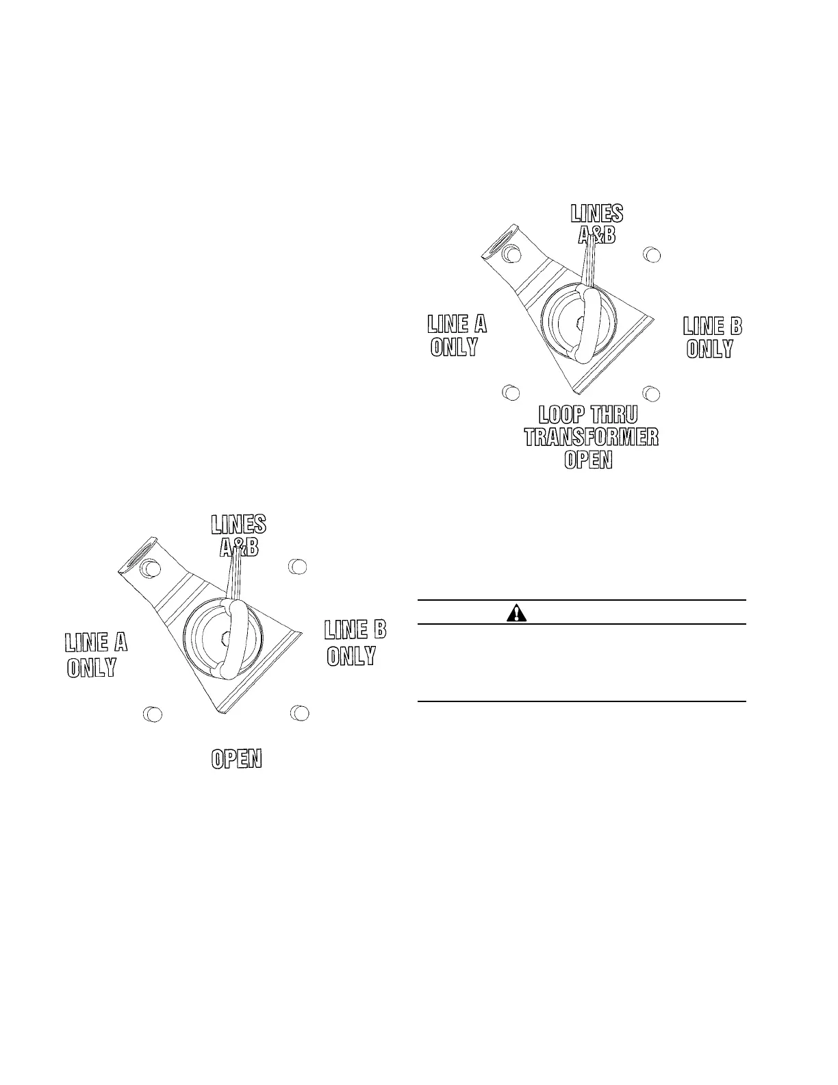
The following is a V-blade switch operation example (see
Figure 17):
If “A” is the feeder and it is desired to switch to “B” feeder,
then the V-blade switch can be rotated as follows:
1. Set index stop plate between “line A only” and “Open”.
2. Rotate switch handle counterclockwise to “Open”.
Transformer and loop conductor are now “Open”.
3. Move index plate between “Open” and “line B only”.
4. Rotate switch handle counterclockwise to “line B only”.
Transformer is now energized for “B” feeder.
The following is a T-blade switch operation example (see
Figure 18):
If “A” is the feeder and it is desired to switch to “B” feeder,
the T-blade switch can be rotated as follows:
1. Set index stop plate between “line A only” and “loop
thru transformer open”.
2. Rotate switch handle counterclockwise to “loop thru
transformer open”. The transformer is now “OPEN” and
the loop conductor is electrically connected.
3. Move index plate between “loop thru transformer
open”” and “line b only”.
4. Rotate switch handle counterclockwise to “line b only”.
The transformer is now energized for “B” feeder.
For switch ratings and additional switch configurations
refer to Catalog Section CA800005EN, Four-Position
Sectionalizing Loadbreak Switches.
Tap-changer
Transformers equipped with a tap-changer can be changed
from one operating voltage to another. The transformer
must be de-energized and grounded before the tap-changer
is operated. Operating voltages accessible through use of
the tap-changer are indicated on the transformer nameplate.
On most three-phase pad-mounted transformers equipped
with tap-changers, the tap-changer operating handle
is located on the faceplate in the high-voltage terminal
compartment.
The standard style of tap-changer will have a hotstick-
operable handle. There are two styles of tap-changer
with this type of handle, each requiring a slightly different
method for changing tap settings.
Figure 17. V-blade four-position sectionalizing switch
handle and index plate.
Figure 18. T-blade four-position sectionalizing switch
handle and index plate.
WARNING
Hazardous voltage. Can cause severe injury, death,
or damage to equipment. De-energize transformer
from a remote upstream source before operating non-
loadbreak tap-changers, dual-voltage switches, or
delta-wye switches.
12 Three-phase pad-mounted compartmental type installation and maintenance instructions MN202001EN August 2015

 Loading...


