Vacuum fault interrupter (VFI)
Eaton’s Cooper Power series VFI transformers utilize
vacuum interrupters to provide fault current interruption and
load make/break switching capabilities. The VFI transformer
uses the same technology used in Eaton’s Cooper Power
series VFI pad-mounted switchgear.
VFI transformers can be specified for either transformer
protection or loop protection. A VFI transformer with
transformer protection protects the transformer and
provides proper coordination with upstream protective
devices. A VFI transformer with loop protection protects
the loop or downstream section of a feeder. Consequently,
when a fault occurs downstream, the VFI breaker trips and
isolates the fault, leaving the transformer load uninterrupted.
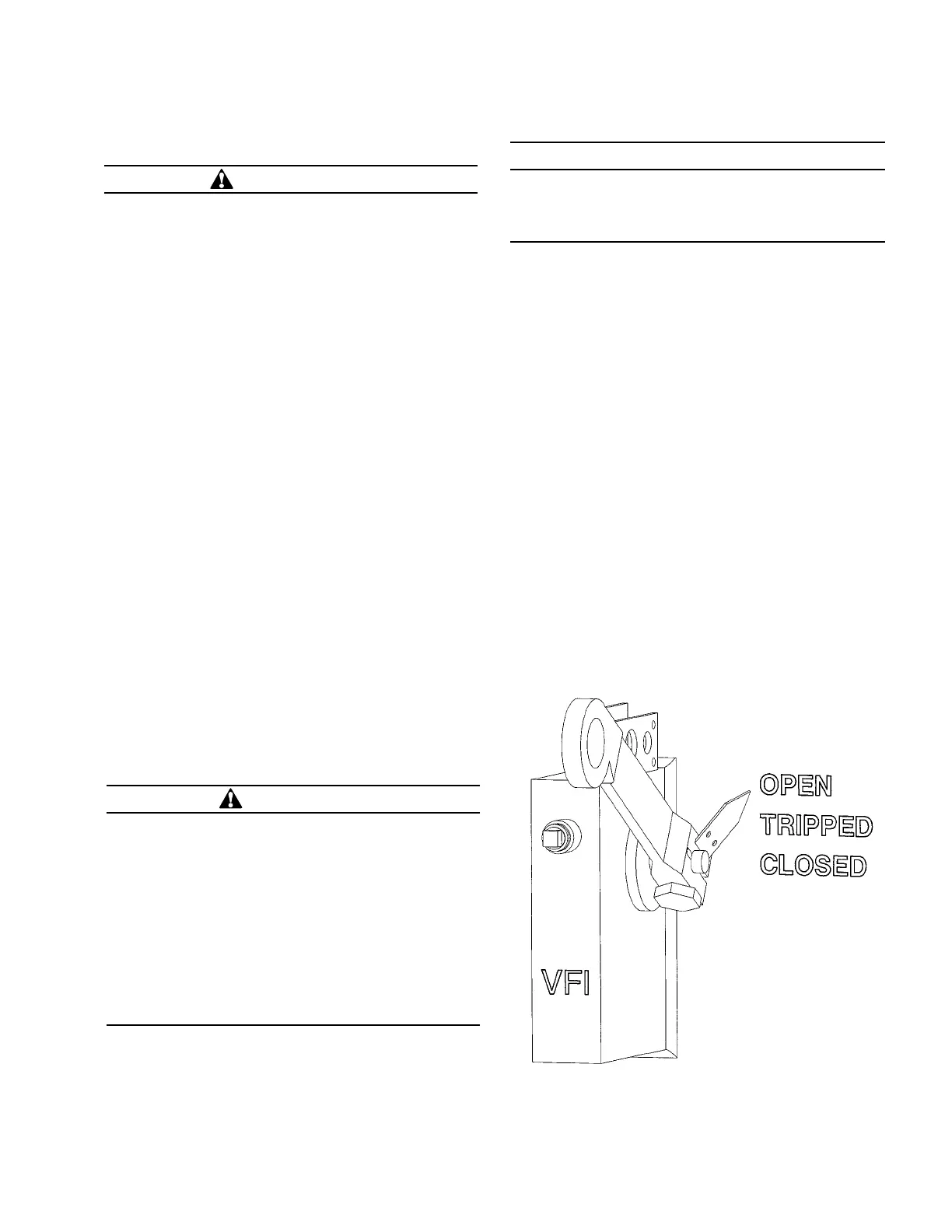
The VFI interrupter mechanism in a VFI transformer has a
hotstick-operable handle located on the faceplate of the
transformer, with the operating mechanisms configured
for ganged three-phase operation (see Figure 24). The VFI
interrupter mechanism is opened by pulling the operation
handle down to the open position. The VFI interrupter
mechanism is closed by briskly pushing the handle up,
into the closed position. If the VFI interrupter mechanism
has tripped as the result of a fault or overload condition,
the mechanism must be reset before it can be closed. To
reset the mechanism, firmly pull the operation handle down
toward the ground until the latch resets. After the latch has
been successfully re-set, the VFI interrupter mechanism can
be closed normally.
Figure 24. VFI operating handle.
IMPORTANT
For 75 °C AWR transformers, applications with
maximum ambient temperatures exceeding 30 °C or
loading in excess of nameplate rating, contact your
Eaton representative.
WARNING
Hazardous voltage. Can cause severe injury, death, or
damage to equipment.
• Do not operate loadbreak equipment if a fault
condition is suspected. Doing so can cause an
explosion or fire.
• Use a hotstick to operate transformer loadbreak
equipment.
• After operating transformer loadbreak equipment,
check that voltages at transformer terminals are
the expected values. Checking voltages verifies that
loadbreak equipment operated properly and that
electrical circuit conditions are as expected.
• Before servicing transformer secondary connected
equipment, verify that all transformer secondary
terminals have zero voltage and ground the
transformer secondary terminals following industry
accepted safe grounding practices. Grounding
secondary terminals protects against situations such
as a standby generator energizing transformer from
the secondary circuit.
• Before servicing transformer, ALWAYS de-energize
the transformer from a remote upstream source and
then proceed to ground all primary and secondary
transformer terminals following industry accepted
safe grounding practices. Grounding secondary
terminals protects against situations such as a
standby generator energizing transformer from the
secondary circuit.
• Follow industry accepted safety practices. Utilize
protective clothing and equipment when working
with loadbreak equipment.
WARNING
Three-phase pad-mounted transformers use
conventional transformer oil, R-Temp fluid, or
Envirotemp™ FR3™ fluid for an insulating liquid. When
the insulating liquid temperature is less than -20 °C
(-4 °F) for conventional transformer oil, less than 0 °C
(32 °F) for R-Temp fluid or less than -10 °C (14 °F) for
Envirotemp™ FR3™ fluid, viscosity is reduced, which
may reduce make and break capabilities of loadbreak
devices. Below these temperatures, under-oil loadbreak
accessories should not be used to make or break a
load. Instead, de-energize transformer from a remote
upstream source before operating under-oil loadbreak
devices.
15Three-phase pad-mounted compartmental type installation and maintenance instructions MN202001EN August 2015

 Loading...


