12
Replacement of Cover Gasket for Padmount Switchgear Side-Hinge-2 Models
FIELD SERVICE INSTRUCTIONS MN285009EN April 2019
11. Reinstall the cover
11.1 While the RTV is forming a skin:
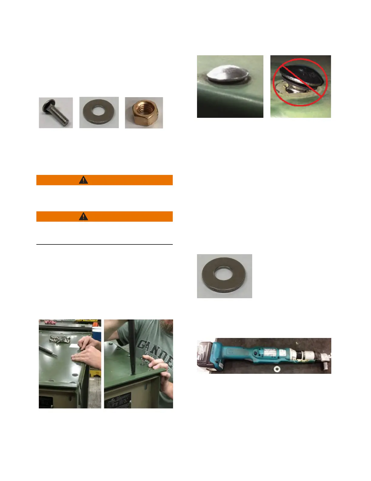
11.1.1 Gather the new Cover bolts, SS Belleville
Washers, and Silicon Bronze nuts.
Figure 53.
11.2 After the RTV has formed a skin, lift the cover and
position it over the main switchgear tank opening in its
original orientation (identified by lining up the blue tape
you applied to the cover and tank in step 6.1).
WARNING
Heavy object. To avoid muscle strain or back injury,
use lifting aids and proper lifting technique when
lifting tank cover.
WARNING
Pinch point. Fingers can be pinched between cover
and tank flange when reinstalling cover. Use cover
lifting tool when reinstalling cover.
11.3 Place the cover bolt and gasket assembly into each of
the cover holes in the following order:
First: the four corners
Next: the center of each side
Last: all remaining holes
ote:N Use an IX-577 alignment bar (altered Proto
J2120 aligning bar) or equivalent to align the
holes, if needed.
Figure 54.
Figure 55. Figure 56.
ote:N You have a maximum working time of
25minutes to install all of the cover bolts
before the RTV sets up. Hand-assemble SS
Belleville washers and Silicon Bronze nuts to all
cover bolts finger-tight.
ote:N The RTV should be wet during this process.
Wipe excess RTV on the surfaces of the tank
and cover off with a shop towel.
ote:N The heads of the carriage bolts should be flush
to the surface of the cover. If they are not flush,
reposition the cover and/or remove all bolts,
raise the cover, and reposition it (Figure 55 and
Figure 56).
ote:N The Belleville washers’ concave surface
must be facing up against the mating surface
(Figure 57).
Figure 57.
11.4 Obtain a Makita BFL300FZ pre-set torque nut runner
set to 18 ft-lbs and Proto MC10568000 9/16-inch
impact socket (or equivalent tools).
Figure 58.

 Loading...


