17type vsa12, vsa12b, vsa16, vsa20, and vsa20a operation and installation instructions MN280063EN May 2017
High-potential withstand testing
WARNING
Hazardous voltage. The switchgear (apparatus and
control) and high-voltage transformer must be in a test
cage or similar protected area to prevent accidental
contact with the high-voltage parts.
Solidly ground all equipment. Failure to comply can
result in death, severe personal injury, and equipment
damage.
T221.5
CAUTION
Radiation. At voltages up to the specified test voltages,
the radiation emitted by the vacuum interrupter is
negligible. However, above these voltages, radiation
injurious to personnel can be emitted. See “Service
Information S280-90-1, Vacuum Interrupter Withstand
Test Voltage Ratings Information” for further
information.
G109.2
The high-potential withstand test provides information on
the dielectric condition of the recloser and the vacuum
integrity of the interrupters. Use the following procedures
to perform high-potential withstand tests at 37.5 kV rms
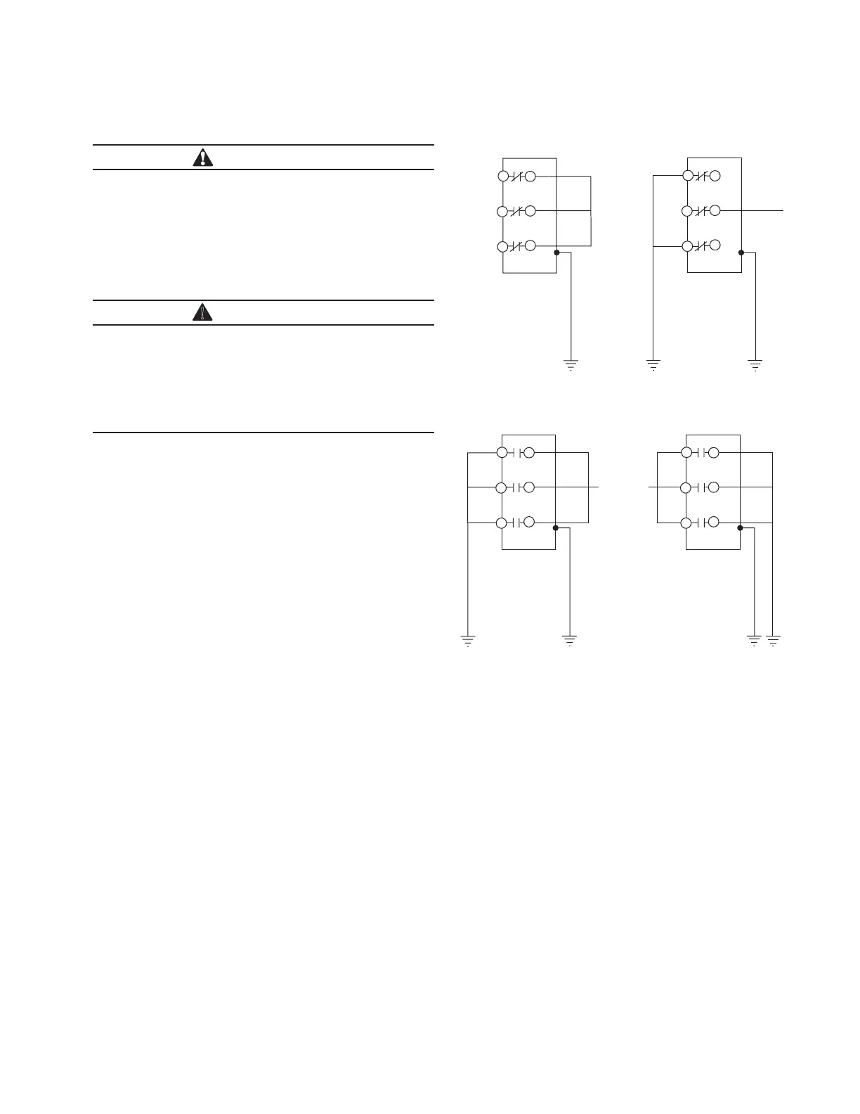
60 Hz or at 50 kV, for 60 seconds. See Figure 16 for test
connection diagrams.
Test 1
1. Close the recloser contacts.
2. Ground the recloser.
3. Connect terminals 2, 4, and 6 together.
4. Apply proper test voltage to terminals 2, 4, and 6.
5. The recloser should withstand the test voltage for 60
seconds.
Test 2
1. Close the recloser contacts.
2. Ground the recloser.
3. Ground Phase A (terminal 2) and Phase C (terminal 6).
4. Apply proper test voltage to Phase B (terminal 3).
5. The recloser should withstand the test voltage for 60
seconds.
Test 3
1. Open the recloser contacts.
2. Ground the recloser.
3. Connect and ground terminals 1, 3, and 5.
4. Connect terminals 2, 4, and 6.
5. Apply proper test voltage to terminals 2, 4, and 6.
Figure 16. Connection diagrams for high-potential
withstand testing.
6. The recloser should withstand the test voltage for 60
seconds.
7. Reverse the connections: ground terminals 2, 4, and 6.
8. Apply test voltage to terminals 1, 3, and 5 for 60
seconds.
9. The recloser should withstand the test voltage for 60
seconds.
1
3
5
2
4
6
ac
TEST 1
PHASE TO GROUND
1
3
5
2
4
6
ac
TEST 2
PHASE TO PHASE
1
3
5
2
4
6
ac
OPEN CONTACT
1
3
5
2
4
6
ac
OPEN CONTACT
TEST 3
 Loading...