12
Controller Network (CNET) overview
PRC-E Series Instruction Manual MN014003EN August 2015 www.eaton.com
The PRCSOC is connected to the PRC system via the CNET
controller network (see Figure 18). Status and command
signals are sent to the PRC system using Pow-R-Command
peer-to-peer protocol.
The PRCSOC features include:
60 low voltage two-wire switch inputs for connecting wall
stations, occupancy sensors, and control relay outputs
from building management systems
Eight low voltage two-wire universal (digital or analog)
inputs. Analog field devices like light level sensors with
0–5 Vdc outputs can be connected for dimming and
daylight harvesting applications
Three low voltage 0–10 Vdc analog outputs for controlling
fluorescent and LED light fixtures equipped dimming
circuitry. Maximum of 40 devices per output with
required dimmer cable (part number 926C162G01)
16 low voltage two-wire 24 Vdc outputs to power
status LEDs (20 mA maximum)
Available option to add 32 low voltage two-wire 24 Vdc
outputs to power status LEDs (20 mA maximum)
External 15 Vdc power source for powering occupancy
and light level sensors and PRC auxiliary devices
(200 mA maximum)
Connects to PRC RS-485 controller network
Communicates to the PRC system using Pow-R-Command
peer-to-peer protocol
Configurable using PRC Lighting Optimization Software
Provided in a NEMA 1 enclosure
120/277 Vac supply voltage
Not compatible with PRC750(E) controllers
Catalog Number Description Part Number
PRCSOCC PRC SOC in an ext. cabinet,
120 V /277 V
42C4780G01
PRCSOCEC PRC SOC in an ext. cabinet,
no power supply
42C4780G02
PRCSOCECO PRC SOC in an ext. cabinet,
120 V / 277 V with pilot output card
42C4780G03
Controller Network (CNET) overview
The PRC-E Series controllers have RS-485 controller network
(CNET) and Ethernet communications capabilities providing
remote programming, monitoring, and override functions.
Using the Pow-R-Command peer-to-peer communications
protocol, each controller connected to the CNET network
can transmit and receive messages among the connected
controllers. Not available in PRC750E controllers.
ote:N Configuring the controller with a unique network
address, between 1 and 120, is required before
establishing communications over the network.
A PRC-E controller address configuration can be
accomplished by using the following methods:
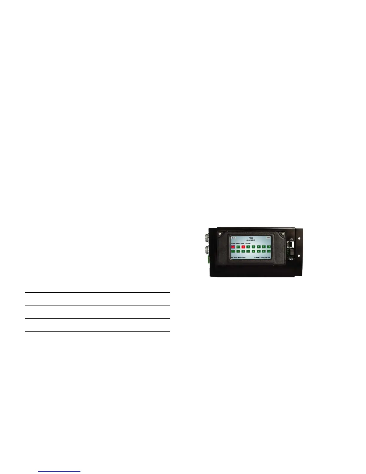
Optional backlit color LCD touchscreen display (refer to
“LCD Touchscreen Display Programming” section on
page 17 of this document)
Personal computer direct connection to controller
Maintenance Port (refer to “Connecting personal computer
to controller Maintenance Port” section on page 15
See Figure 19 for controller color LCD touchscreen display
and Maintenance Port locations.
Figure 19. PRC-E Series Controller

 Loading...


