78
Appendix A: Breaker Control Bus (BCB) installation
PRC-E Series Instruction Manual MN014003EN August 2015 www.eaton.com
Appendix A: Breaker Control Bus (BCB)
installation
The BCB is designed to fit easily into the Eaton PRL1a and
PRL2a panelboard models. The standard 1a/2a application
can be converted to a PRCEP panelboard by installing
one or two BCB modules. A factory-produced PRCEP
panelboard should contain one or two pre-installed BCB
modules. A factory-installed SLAN cable will be included
to connected right and left BCBs. If this was not a factory-
ordered option, it will be necessary to install the BCB into
the Pow-R-Line 1a/2a panelboard containing BABRSP or
GHQRD circuit breakers. BCB kits were developed for these
retrofit applications. Pre-made BCB-to-BCB SLAN cables can
be selected from the table below.
Description Catalog Number
Controller-to-BCB / 42-circuit panelboard PRCSLAN42
Controller-to-BCB / 30-circuit panelboard PRCSLAN30
Controller-to-BCB / 18-circuit panelboard PRCSLAN18
Controller-to-BCB / 42-circuit w/right-side BCB only PRCSLAN42R
Controller-to-BCB / 30-circuit w/right-side BCB only PRCSLAN30R
Controller-to-BCB / 18-circuit w/right-side BCB only PRCSLAN18R
BCB-to-BCB / 42-circuit panelboard PRCSLAN42B
BCB-to-BCB / 30-circuit panelboard PRCSLAN30B
BCB-to-BCB / 18-circuit panelboard PRCSLAN18B
BCB retrofit kits
BCB retrofit kits include a BCB, mounting screws, and
connector covers. The BCB unit is interchangeable between
the left side and right side of the panelboard, therefore the
retrofit kit is configured to cover one side of a 42-, 30-, or
18-circuit panelboard. The BCB kits available are in 21-, 15-,
and 9-circuit configurations. An example of use, a 30-circuit
panelboard with controllable circuit breakers on both sides
would require two 15-circuit retrofit kits.
Figure 27. 15-Circuit Breaker BCB Retrofit Kit
m WARNING
DISCONNECT THE MAIN POWER FROM THE PANELBOARD. THE
FOLLOWING PROCEDURES REQUIRE REMOVAL OF PROTECTIVE
COVERS AND SHIELDS RESULTING IN POSSIBLE EXPOSURE TO
DANGEROUS AND/OR DEADLY VOLTAGES!
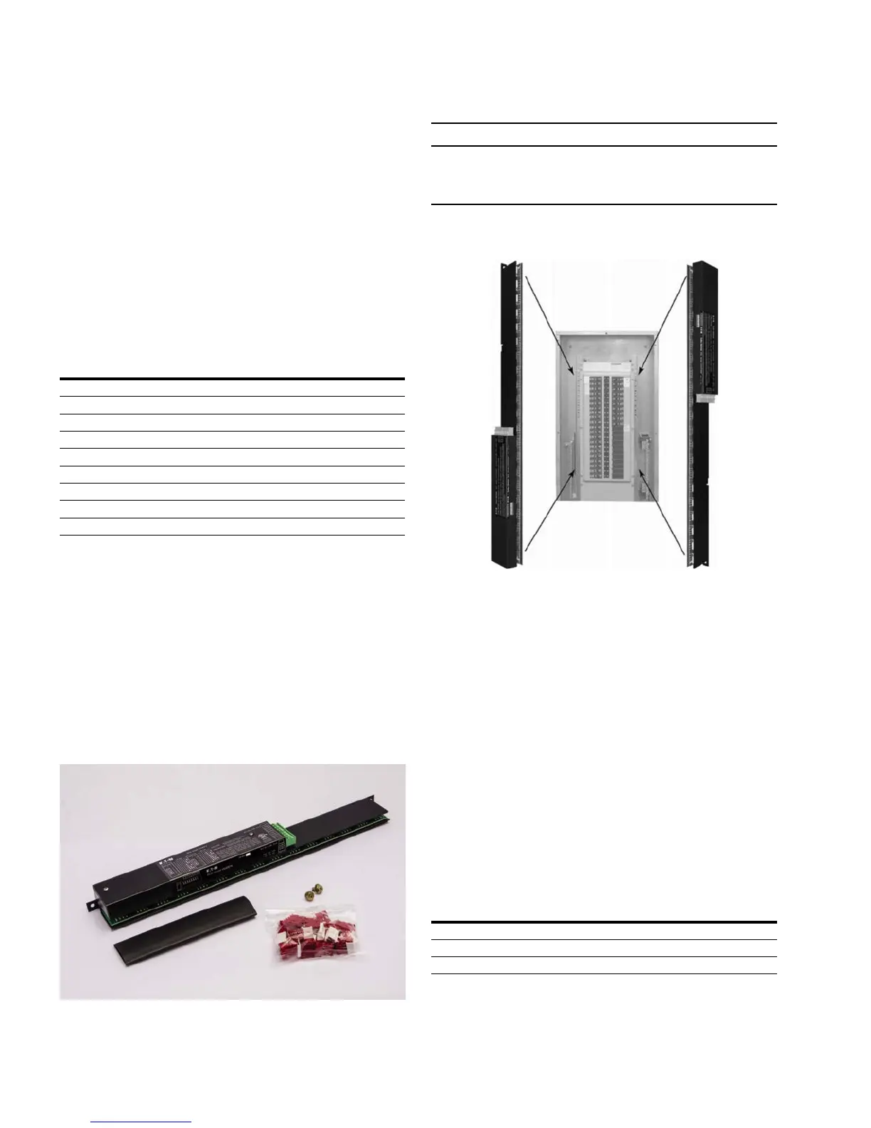
Figure 28. BCB Orientation
The BCB is designed to fit either side of a Pow-R-Line 1a
or 2a panelboard. The PRC-E Series Web browser interface,
color LCD touch screen, or optional Lighting Optimization
Software (LOS) is used to configure the BCB for proper
association with circuits in the panelboard. Refer to the
“LCD Programming” and Web page programming sections
of this documentation for assistance with configuring and
orienting the BCB.
Step 1. Remove the trim piece.
Different designs and options have different trim pieces.
It is beyond the scope of this document to describe each
possibility. Please refer to the Instruction Leaflet provided
with the panelboard.
Step 2. Remove the deadfront cover.
Remove the four screws holding the perforated frame to the
panelboard chassis. Figure 29 shows a typical detail of the
top-left screw to be removed. There should be an identical
screw at, or near, each corner of the deadfront cover.
Description Catalog Number
Breaker control bus (BCB)—21 circuits—retrofit kit PRC1000BCB-21R
Breaker control bus (BCB)—15 circuits—retrofit kit PRC1000BCB-15R
Breaker control bus (BCB)—9 circuits—retrofit kit PRC1000BCB-9R

 Loading...


