Apex2 I/O Board Installation
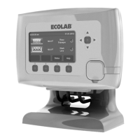
1. Install Apex2 I/O enclosure cover
a. Align cover with the stainless steel hinge pin. Press forward firmly
on the cover to snap it into place. If necessary, use pliers to squeeze
cover assembly onto hinge pin.
NOTE: Avoid twisting the front cover as this may damage the Apex2 I/O board
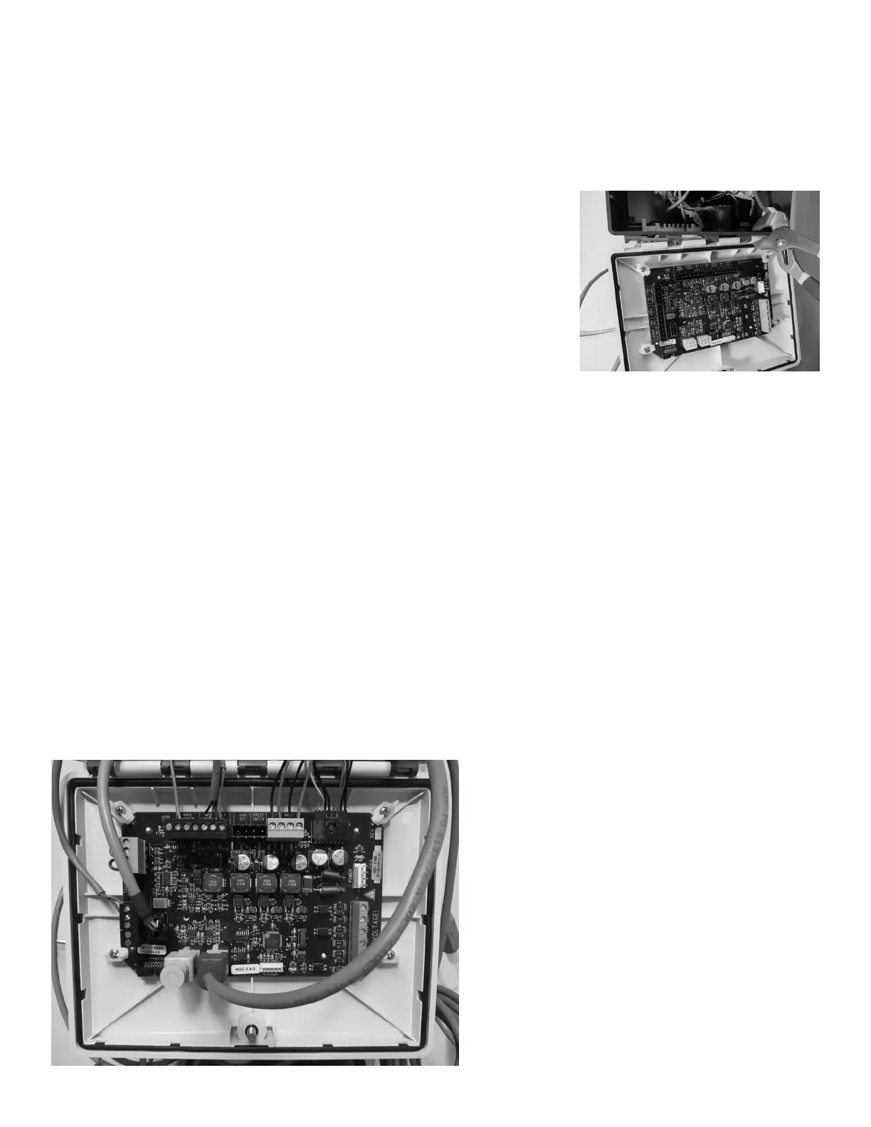
2. Install Apex2 I/O Board Connections
Refer to the I/O Board diagram, Figure 4.11
a. Install the 7-pin Phoenix connector (Det Lid Switch, Rinse Thermistor,
and Rinse Sensor)
b. Rinse Aid Out-of-Product Signal Wire (connect to location ‘S’ on Rinse
Sensor Connector)
c. Install the 5-pin Phoenix connector (‘Network’ and ‘Rinse Max’) to the
‘Network’ and ‘Rinse Dispenser’ pin locations on the Apex2 board
d. Install the 4-pin Phoenix connector for the (‘Pressure Switch’ and ‘San
Out’)
e. Install the supplied 4-pin jumpered Phoenix connector in the ‘Rinse Lid
Switch’ and ‘San Lid Switch’ location on the Apex 2 I/O board
f. Connect the Inductive Probe to the Apex2 I/O board. Wrap excess cable
outside of the I/O enclosure.
g. Connect the RS-485 cable into one of the open RS-485 connectors on
the Apex2 I/O board. Wrap excess cable outside the I/O enclosure.
Install the RS-485 terminating plug assembly into the other connector.
h. Cut the rinse motor wires from the connector
i. Strip wire ends
ii. Insert into the supplied 4-pin Phoenix connector in the ‘Rinse Out’
iii. Insert positive(red) into ‘+’ and negative(black) into ‘-‘
iv. Tighten screw connections
i. Cut the detergent valve wires from the connector
v. Strip wire ends
vi. Insert into the supplied 4-pin Phoenix connector in the ‘Det Out’
vii. Insert positive(brown) into ‘+’ and negative(black) into ‘-‘
viii. Tighten screw connections
j. Connect the power supply to the Apex2 I/O Board, then close enclosure
cover.
16
Figure 4.21
Figure 4.22
 Loading...