8
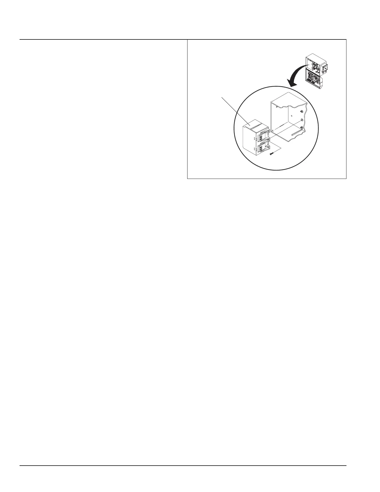
Figure 5-2
5.2 440 Volt Machine Power Supply
NOTE: Most 440 volt machines will provide a source of
115 or 220 volts for the dispenser supply. If only 440 volts
is available, it will be necessary to externally mount two
440 to 24 volt transformers. The transformers shipped
with the GeoCenter will not be used, and it is suggested
that these transformers not be installed.
1. Remove the built-in transformers from the GeoCenter
Cabinet, refer to Figure 5-2.
2. Connect one of the 24 volt leads, using a butt-
connector or a wire nut, from the external transformer
to the two VIOLET wires normally connected to the top
transformer.
3. Connect the single ORANGE wire to the other transformer
lead.
4. Connect one of the 24 volt leads using a butt connector
to one of the GRAY wires normally connected to the
bottom transformer.
5. Connect the other wire in the same manner.
5.3 S-2000 Sensor Wire Connections
1. Attach the BROWN wire to terminal #15, refer to Figure
5-1.
5. Attach the RED wire to terminal #11.
6. Ensure JP1 and JP2 on the PC Board are only installed
on one pin.
5.4 Geosystem Detergent Dispenser Wiring
Connections
The Geosystem Detergent Dispenser features a switch on
the lid to interrupt detergent feed if the lid is opened. (Use
a 2 conductor cable between the GeoCenter and Detergent
units).
At the GeoCenter (Refer to Figure 5-1 on page 7):
• Wire nut the leads from the 2 conductor cable to the
5.5 Geosystem Solid Rinse Reservoir Connec-
tions
The Geosystem Solid Rinse injector reservoir features a
lid switch to interrupt water spray to the rinse additive if the
lid is opened.
TRANSFORMER
ASSEMBLY
-
nals #1 & #2 on the green Phoenix connector.
• The black and red wires are connected to terminals #4
IMPORTANT: RED must be connected to #7. BLACK
must connect to #4.
NOTE: This refers only to the Solid Rinse Additive dis-
penser. Hook up the Geomax unit for use with liquid
rinse additives.
5.6 VANGUARD Wash Max Wiring Connec-
tions
The VANGUARD Wash Max features a safety switch on
the lid to interrupt detergent feed if the lid is opened. A 20'
two conductor cable is connected to the unit to help instal-
lation.
At the VANGUARD GeoCenter (Refer to Figure 5-1 on
BLUE wires provided with the wire nuts.
5.7 Two Pole Probe Wire Connections
1. At the Two Pole Probe, connect the cell wiring to the
2 screws terminals. Leave enough slack in the wire to
allow removal of the cell from the connector without
having to disconnect the wire (refer to Figure 5-1).
2. At the GeoCenter connect the cell wires to TERMINALS
#10 and #11.
3. Ensure JP2 on the PC Board is installed in the "S26"
position.
 Loading...