11
Installing the Motherboard
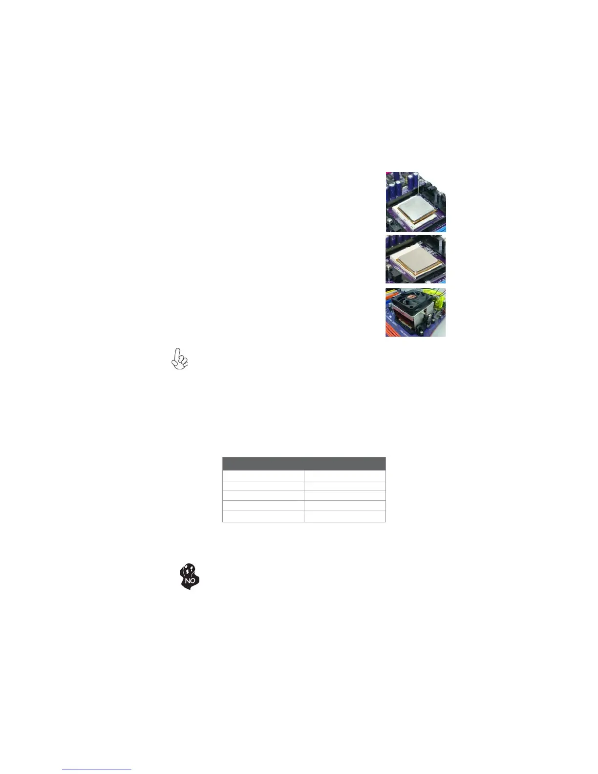
CPU Installation Procedure
The following illustration shows CPU installation components.
To achieve better airflow rates and heat dissipation, we suggest that you
use a high quality fan with 4800 rpm at least. CPU fan and heatsink
installation procedures may vary with the type of CPU fan/heatsink sup-
plied. The form and size of fan/heatsink may also vary.
1 Unhook the locking lever of the CPU socket. Pull the
locking lever away from the socket and raising it to
the upright position.
2 Match the pin1 corner marked as the beveled edge
on the CPU with the pin1 corner on the socket.
Insert the CPU into the socket. Do not use force.
3 Push the locking lever down and hook it under the
latch on the edge of socket.
4 Apply thermal grease to the top of the CPU.
5 Install the cooling fan/heatsink unit onto the CPU,
and secure them all onto the socket base.
6 Plug the CPU fan power cable into the CPU fan
connector (CPU_FAN) on the motherboard.
Installing Memory Modules
This motherboard accommodates four memory modules. It can support four 240-pin
DDR2 1066 (AM2+)/800/667/533/400. The total memory capacity is 32 GB*.
DDR2 SDRAM memory module table
Do not remove any memory module from its antistatic packaging until
you are ready to install it on the motherboard. Handle the modules only
by their edges. Do not touch the components or metal parts. Always
wear a grounding strap when you handle the modules.
You must install at least one module in any of the four slots. Each module can be
installed with 8 GB of memory; total memory capacity is 32 GB*.
Memory module Memory Bus
DDR2 400 200 MHz
DDR2 533 266 MHz
DDR2 667 333 MHz
DDR2 800 400 MHz
DDR2 1066 533 MHz
 Loading...