Installation
Notes
• The module is shipped from the factory as an assembled
unit; it contains no user-serviceable parts and should not
be disassembled.
• This module does not operate without electrical power. As
fires frequently cause power interruption, discuss further
safeguards with the local fire protection specialist.
Install in accordance with all applicable local codes and
standards and the local authority having jurisdiction.
To install the module:
1. Wire in accordance with “Wiring” below.
2. Write the address assigned to the module on the label
provided, and then apply the label to the module. Remove
the serial number label from the detector and, and then
attach it to the project documentation.
3. Using the screw provided, mount the wall plate on the
module. See Figure 1 for mounting details.
4. Using the screws provided, mount the wall plate (with the
module attached) on one of the compatible electrical
boxes listed in “Specifications” on page 6.
Figure 1: Mounting the GSA-CC1 module
(1) Compatible electrical box
(2)
2-gang ring cover (if required)
(4) Wall plate, (dual-gang)
(5) #6-32 × 5/8 screw (4X)
(6) #4 × 1/2 self-tapping screw
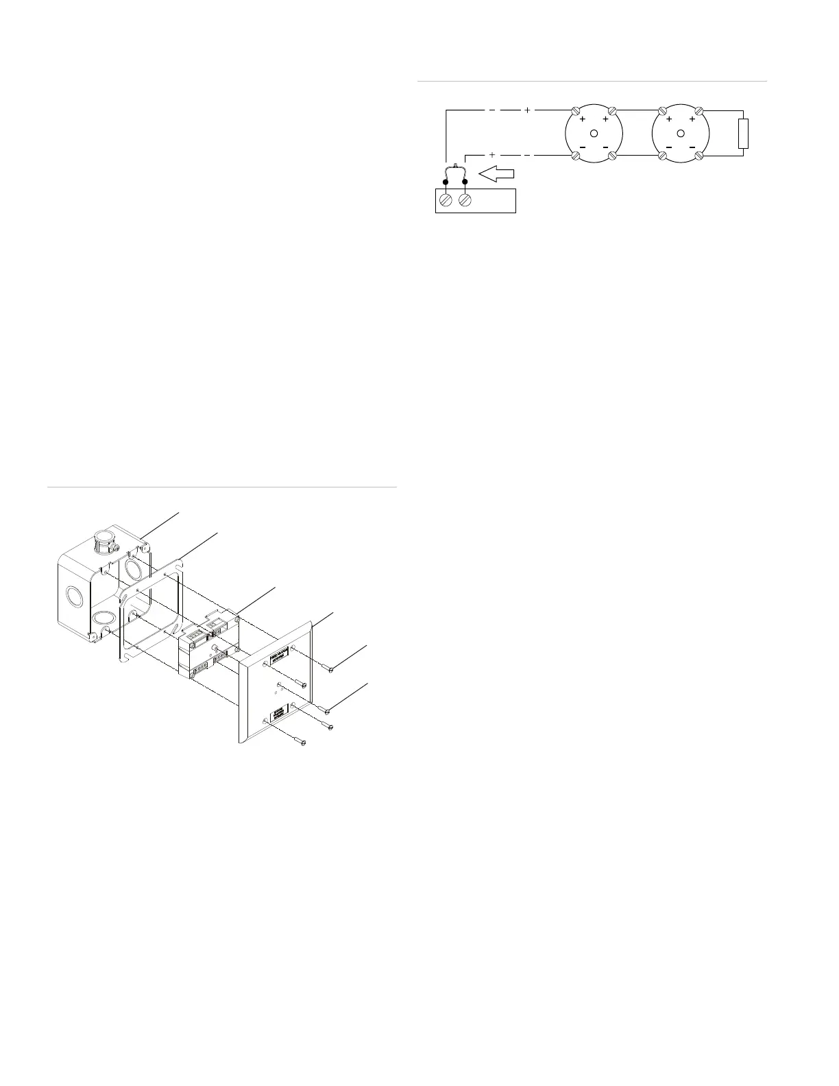
Protection from transient spikes
For installations in which the output circuit connects to
electromechanical bells or horns, install a Bipolar Transient
Protector (P/N 235196P) to prevent inductive loads from
causing transient spikes.
To install a bipolar transient protector:
1. Install the transient protector on the output of the module.
Fit the transient protector into the electrical box with the
module. See Figure 2.
Figure 2: Bell circuit showing bipolar transient protector
placement
Wiring
Wire in accordance with applicable requirements of the latest
editions of the local codes and standards and the local
authority having jurisdiction.
Strip 1/4 in. (about 6 mm) from the ends of all wires that
connect to the terminal block of the module.
Note: When stripping wire ends, exposing more wire may
cause a ground fault; exposing less wire may result in a faulty
connection.
General wiring notes
• Refer to the Signature loop controller installation sheet for
SLC wiring specifications. Refer to the firefighter phone
installation sheet for additional details.
• Each terminal on the module is limited to a single
conductor.
• Test resistors are supplied with the GSA-CC1 to prevent
trouble signals on unused circuits during installation.
When connecting field wires, remove the test resistors and
install a UL/ULC Listed 47 kΩ EOLR at the end of the
circuit.
• The module does not support conventional smoke
detectors.
Riser notes
• For maximum line impedance, refer to the installation
manual for the fire alarm panel. Maximum circuit
capacitance is 0.1 µF.
• If the riser is used for more than one notification zone,
install in accordance with the survivability from attack by
fire requirements in NFPA 72 National Fire Alarm and
Signaling Code.
• Circuit and riser wiring is different when four-state
firefighter telephones are installed on three-state circuits.
Before replacing a GSA-CC1 module, tag the wires to
ensure correct reconnection.
• The GSA-CC1 module does not supervise the riser; the
fire alarm control panel provides this function.
2 / 6 P/N P-047550-1802-EN • REV 04 • ISS 23JUN15

 Loading...


