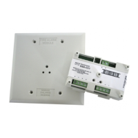
Specifications
15.20 to 19.95 VDC
Standby
Activated
310 µA
135 µA
Refer to the control panel installation
manual
10 kΩ
Output ratings (special
applications)
24 VDC
25 VRMS audio
70 VRMS audio
EOL resistor value
Circuit resistance
Circuit capacitance
2 A
50 W
35 W
47 kΩ
Refer to the control panel installation
manual
0.1 µF max.
47 kΩ (P/N EOL-47)
Signaling line circuits
Telephone riser circuits
Notification line circuits
Class A, Style 6 or Class B, Style 4
Class B, Style 4
Class B, Style Y
Compatible electrical boxes
2-1/2 in. (64 mm) deep dual-gang box;
4 in. square box 1-1/2 in. (38 mm)
deep box with a dual-gang cover
12 to 18 AWG wire (0.75 to 2.5 mm²)
Temperature
Relative humidity
32 to 120°F (0 to 49°C)
0 to 93%, noncondensing
temperature range −4 to 140°F (−20 to 60°C)
Regulatory information
Edwards, A Division of UTC Fire & Security
Americas Corporation, Inc.
8985 Town Center Parkway, Bradenton, FL
34202, USA
The first two digits of the DATE MFG number
(located on the product identification label) are
the year of manufacture.
This device complies with part 15 of the FCC
Rules. Operation is subject to the following two
conditions: (1) This device may not cause
harmful interference, and (2) this device must
accept any interference received, including
interference that may cause undesired operation.
CAN/ULC-S527, UL 864
Contact information
For contact information, see www.utcfireandsecurity.com.
6 / 6 P/N P-047550-1802-EN • REV 04 • ISS 23JUN15

 Loading...