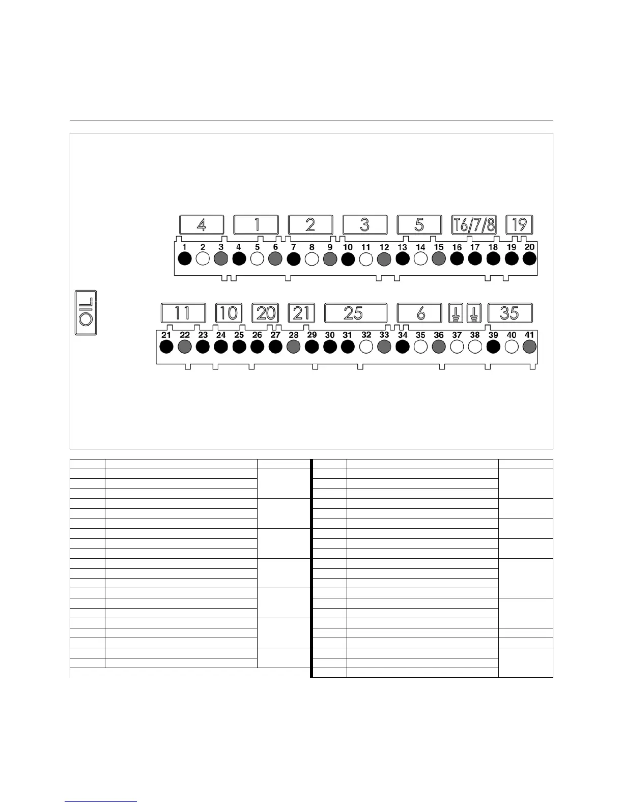
Terminal Description Connector Terminal Description Connector
1 Burner motor live
4
21 Flame monitoring signal
11
2 Earth 22 Neutral
3 Neutral 23 Live
41
st
stage solenoid valve live
1
24 Not used
10
5 Earth 25 Not used
6 Neutral 26 Live
20
72
nd
stage solenoid valve live
2
27 Remote unlocking signal
8 Earth 28 Neutral
21
9 Neutral 29 Signal fault live
10 3
rd
stage solenoid valve live
3
30 Live
25
11 Earth 31 Preheater/release contact
12 Neutral 32 Earth
13 Igniter live
5
33 Neutral
14 Earth 34 Live L1
6
15 Neutral 35 Earth
16 2
nd
stage thermostat phase (T6)
T6/7/8
36 Neutral
17 Signal T7 37 Earth
18 Signal T8 38 Earth
19 1
st
stage thermostat live (T1)
19
39 Pump unit live
35
20 Heating request signal (option T2) 40 Earth
41 Neutral
Operation
Terminal allocation chart
230 Volt connection
 Loading...