T 3000 - T 350
2
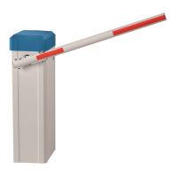
7.5 Boom connector
1. The boom connector can be mounted left or right (factory setting is
right).To fasten the boom connector, plug it without the clamping piece on
the main shaft. Pay attention to a perfect fit of the shaft seal at the
housing. Now connect the clamping piece using the four screws (M12x30
ISO4762). Tighten the screws only so far that an alignment of the boom
connector on the main shaft is still possible.
Drawing 9
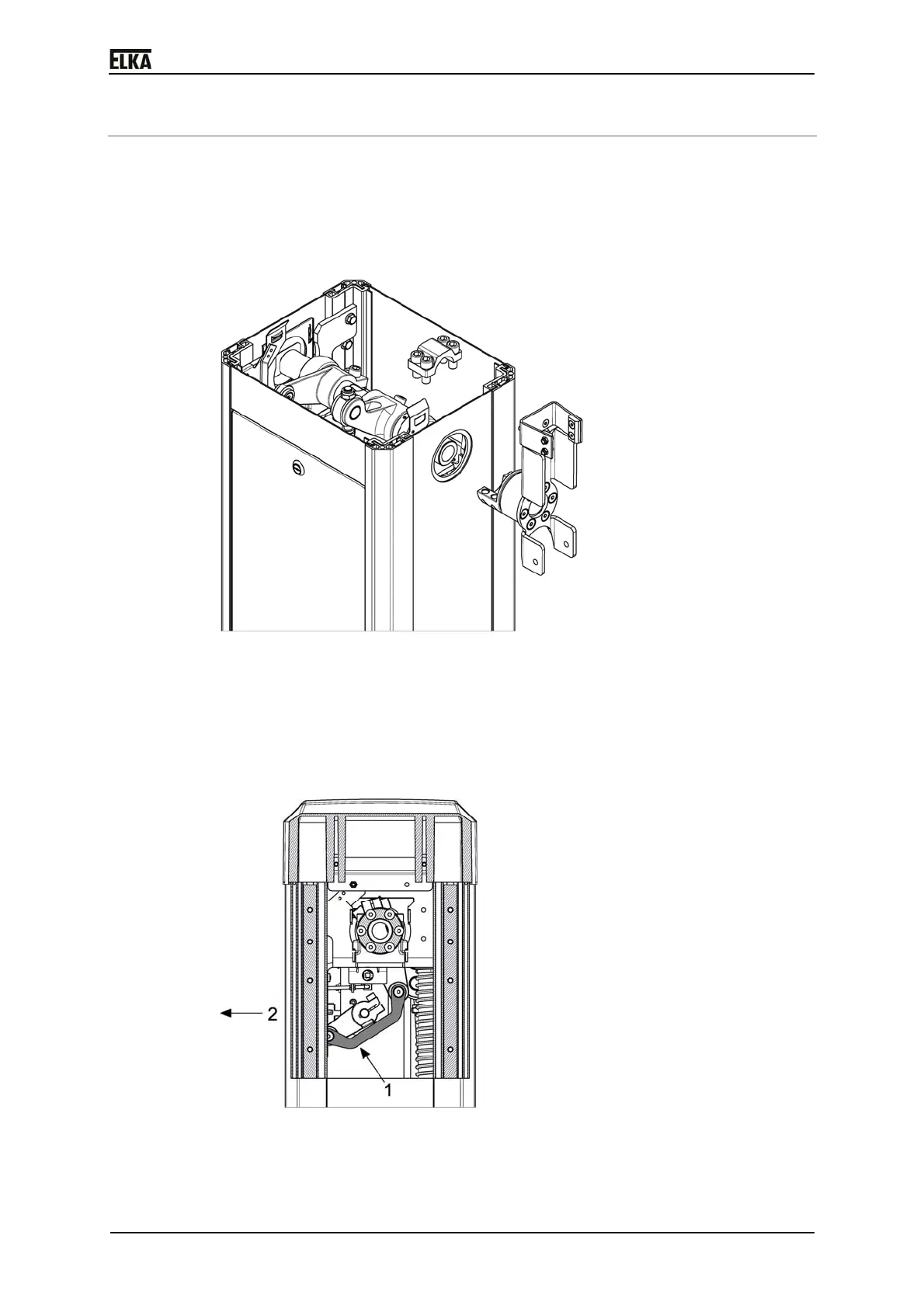
2. The barrier mechanics is preset at the factory so that the barrier boom can
perform a 90° - movement from the vertical to the horizontal position. The
barrier is delivered in open (vertical) position. The drive lever is over the
dead center at the mechanical stop (see drawing below). If necessary,
correct the position by pulling the drive lever (1) in direction OPEN -
towards roadway (arrow 2).
Drawing 10
3. Adjust the boom connector vertically using a water-level.
 Loading...