7
ww w.eltherm.com
Contact us: +49 2736 4413-0 • info@eltherm.com
Operation manual
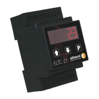
ELTC-21 & ELTC-22
BU-093
Revision 7
Declaration of Conformity
We declare that the described product fully complies with Di-
rectives 2014/35/EU, 2014/30/EU and 2011/65/EU. If you need
a detailed declaration of conformity, please contact us.
ATTENTION
The settings of the controller must be checked during
commissioning.
NOTE
The temperature control device and the temperature sen-
sor(s) should be calibrated against the factory setting during
commissioning if necessary.
i
Notes on commissioning
PARAMETERS AND THEIR MEANING
Parameter Meaning and range
P01
Actual value
display only
P10
Control setpoint
range P13...P14, [5°C]
P11
Switching hysteresis
range 2...10K, [2K]
P12
Minimum standstill
time (relay K1)
0..30 min., [0 min],
resolution 1 min.
P13
Maximum adjustable
setpoint
range P14...+390°C, [+390°C]
P14
Smallest adjustable
setpoint
range -50°C...P13, [0°C]
P20
Sensor type
0 = Pt100, 3-wire, °C (resolution 1K)
[1] = Pt100, 2-wire, °C (resolution 1K)
2 = Pt100, 3-wire, °F (resolution 2°F)
3 = Pt100, 2-wire, °F (resolution 2°F)
P21
Sensor correction
-30...+10K, [0]
P30
Overtemperature alarm
P31...400°C, [400°C]
P31
Undertemperature alarm
-60...P30, [-60°C]
P32
Alarm delay in opera-
tion
0...99 min., [0 min.]
resolution 1 min.
P33
Alarm delay after
switch-on
0...500 min., [0 min.]
0 = relay K2 (active) energizes on sensor
error
Load relay K1 drops in case of sensor
error
[1] = relay K2 (passive) drops in case of
sensor error
Load relay K1 drops in case of sensor
error
P34
Alarm relay mode
(Relay K1 and K2)
2 = K2 works as enable relay
Load relay K1 drops in case of sensor
error
3 = Relay K2 (active) energizes in case of
sensor error
Load relay K1 energizes in case of sensor
error
4 = Relay K2 (passive) drops in case of
sensor error
Load relay K1 energizes in case of sensor
error
5 = K2 works as enable relay
Load relay K1 energizes in case of sensor
error
ATTENTION
P34=3, P34=4 and P34=5 is only permissible for frost pro-
tection applications and use of self-regulating trace heaters.
In [...] the factory settings are indicated.
Mode Enable relay
Mode Alarm relay
In this operating mode (P34=2 or 5), relay K2 switches inde-
pendently of P32 and P33 as soon as the actual value is within
P30 and P31.
(P34 = 0 or 1) : If the actual temperature is below P31 when
the device is started, P33 is used once as the alarm delay to
give more time to the system. In normal operation, P32 is used
as alarm delay.

 Loading...