4-1 FL13.10_DC
CABINET DISASSEMBLY INSTRUCTIONS
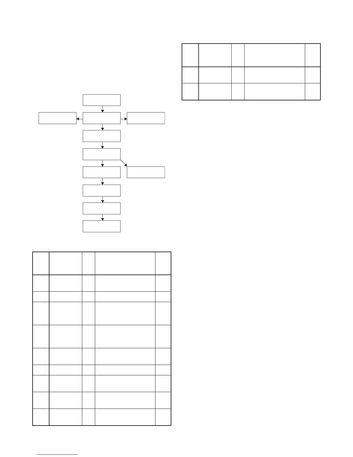
1. Disassembly Flowchart
This flowchart indicates the disassembly steps for the
cabinet parts and the CBA in order to gain access to
items to be serviced. When reassembling, follow the
steps in reverse order. Bend, route and dress the
cables as they were.
2. Disassembly Method
Note:
(1) Order of steps in procedure. When reassembling,
follow the steps in reverse order. These numbers
are also used as the Identification (location) No. of
parts in figures.
(2) Parts to be removed or installed.
(3) Fig. No. showing procedure of part location
(4) Identification of parts to be removed, unhooked,
unlocked, released, unplugged, unclamped, or
desoldered.
P = Spring, L = Locking Tab, S = Screw,
H = Hex Screw, CN = Connector
e.g. 2(S-2) = two Screws of (S-2),
2(L-2) = two Locking Tabs of (L-2)
(5) Refer to the following "Reference Notes in the
Tabl e. "
Important precautions concerning the
LCD Panel Assembly:
When you disassemble/re-assemble the Front
Cabinet or Function CBA Unit
• Be careful not to break the hooks. If you pull with too
much force, the hooks may be damaged.
• Be careful not to scratch the display panel when
assembling.
• Be careful not to scratch the rear frame when
disassembling/re-assembling or when tightening the
screws.
• Make sure the Shield Plate is placed properly.
• The Function CBA Unit and Sensor Lens are fixed in
place by the hooks. Make sure these hooks are not
damaged. Make sure the Function CBA Unit and
Sensor Lens are securely in place when
re-assembling.
• The screw tightening torque must be 6.1lb·in
(7kgf·cm).
• Make sure the tact switches operate normally after
replacing the Front Cabinet, Function CBA Unit,
Sensor Lens, or Shield Plate.
Step/
Loc.
No.
Part
Fig.
No.
Removal Note
[1]
Stand
Assembly
D1 3(S-1) ---
[2] Rear Cover D1 5(S-2), 5(S-3) ---
[3]
Power
Supply
CBA
D2
D5
5(S-4), CN601,
CN501, CN1001
---
[4]
Digital Main
CBA Unit
D2
D5
4(S-5), CN3013,
CN3101, CN3801,
Jack Holder
---
[5]
Stand
Bracket
D3 2(S-6) ---
[6] Speaker D3 ---------------- ---
[7]
Bottom
Cover L
D3 (S-7), (S-8) ---
[8]
Bottom
Cover R
D3 (S-9), (S-10) ---
[9]
LCD Panel
Assembly
D3 ---------------- ---
[2] Rear Cover
[1] Stand
Assembly
[3] Power Supply
CBA
[6] Speaker
[5] Stand Bracket
[9] LCD Panel
Assembly
[10] Front Cabinet
[4] Digital Main
CBA Unit
[7] Bottom
Cover L
[11] Function
CBA Unit
[8] Bottom
Cover R
[10]
Front
Cabinet
D4 10(S-11) 1
[11]
Function
CBA Unit
D4
Sensor Lens, Shield
Plate, Control Plate
1
↓
(1)
↓
(2)
↓
(3)
↓
(4)
↓
(5)
Step/
Loc.
No.
Part
Fig.
No.
Removal Note

 Loading...